# SmartB

# Replace weight sensor

<table border="1" id="bkmrk-czasami-co%C5%9B-si%C4%99-pops" style="border-collapse: collapse; width: 100%; border-width: 1px; border-style: hidden;"><colgroup><col style="width: 50%;"></col><col style="width: 50%;"></col></colgroup><tbody><tr><td style="border-width: 1px;">In this document you will find a description how to replace the weight sensor in the Smartb

</td><td style="border-width: 1px;">You will need:

- a new weight sensor kit
- a set of allen keys
- trimmers
- cutters

</td></tr></tbody></table>

<p class="callout danger">Before replacing disconnect device from the power supply!</p>

---

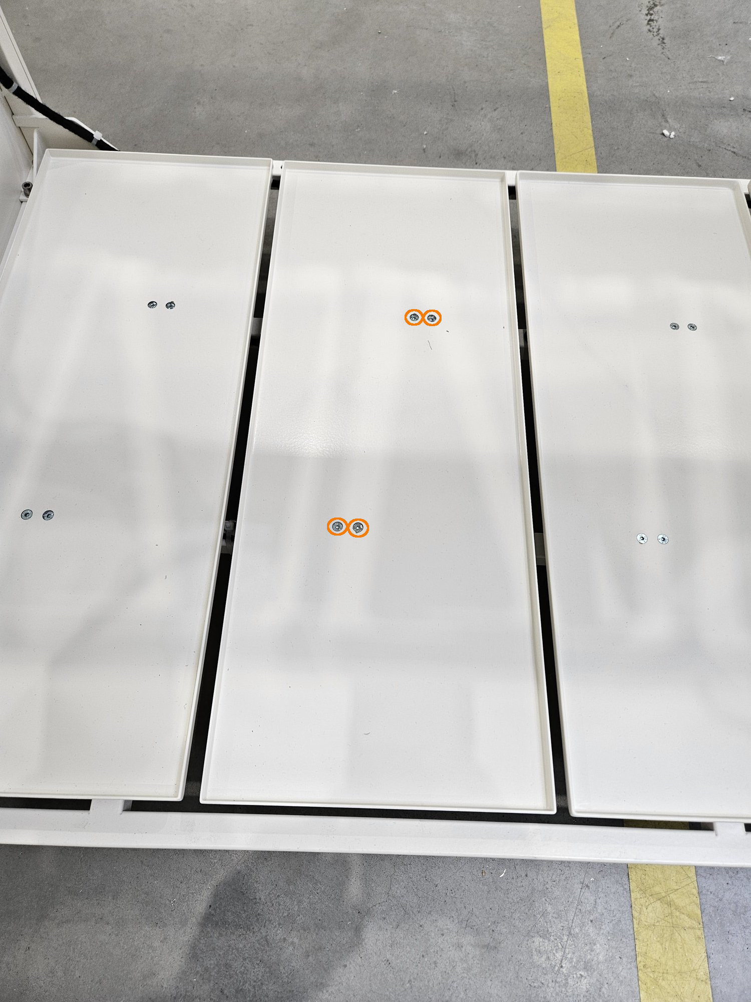
#### **Step 1** Unscrew the top floor 

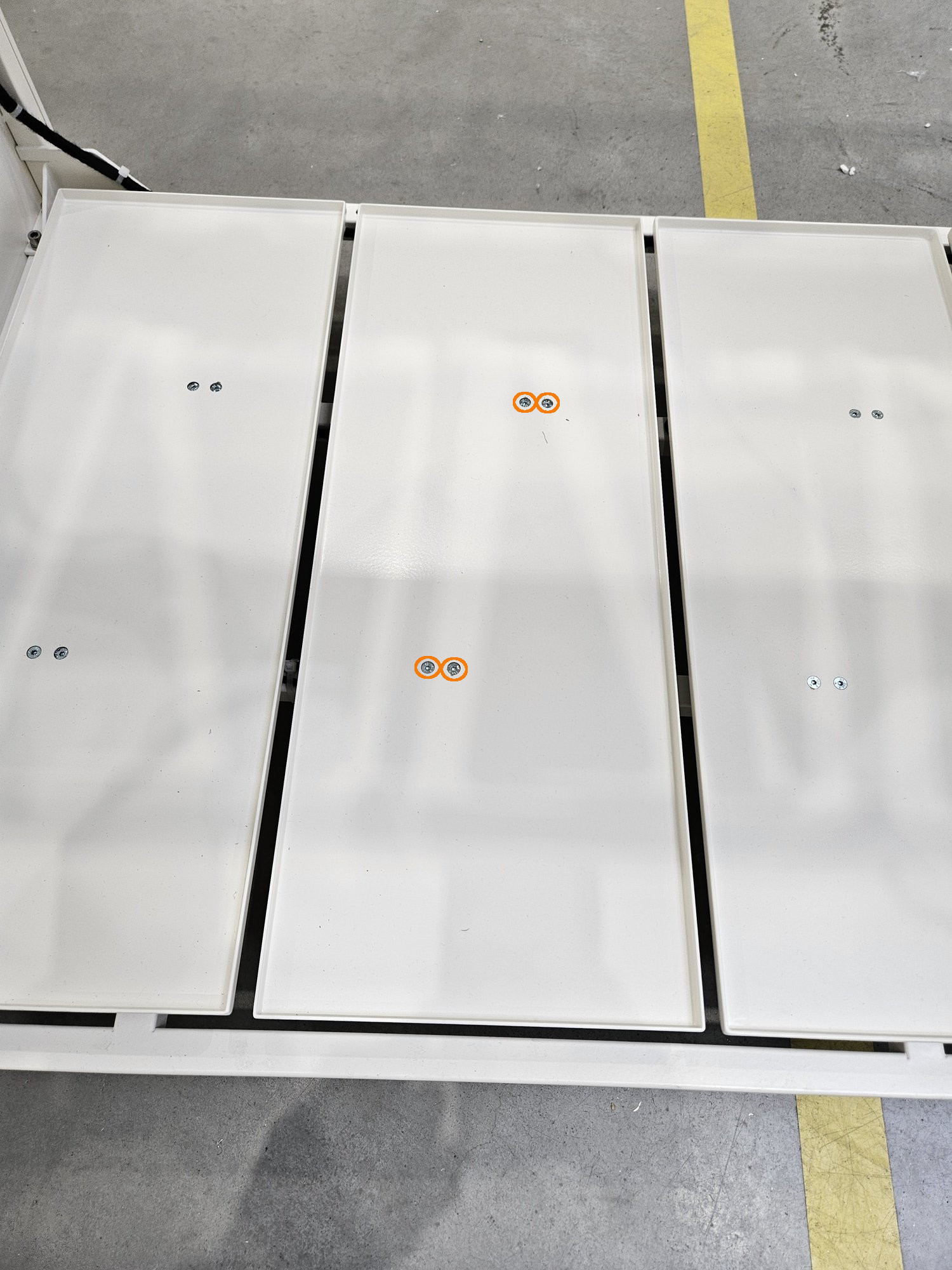
<table border="1" id="bkmrk-the-top-floor-is-bol" style="border-collapse: collapse; width: 100%; border-width: 1px; border-style: hidden;"><colgroup><col style="width: 50%;"></col><col style="width: 50%;"></col></colgroup><tbody><tr><td>- The top floor is bolted directly from the strain gauge beams
- Unscrew the 4 screws marked on the picture

</td><td>[![1.jpg](https://docs.bine.world/uploads/images/gallery/2023-11/scaled-1680-/h6WN2VgvyqWfRjB5-1.jpg)](https://docs.bine.world/uploads/images/gallery/2023-11/h6WN2VgvyqWfRjB5-1.jpg)</td></tr></tbody></table>


---

#### **Step 2** Unplug the sensor

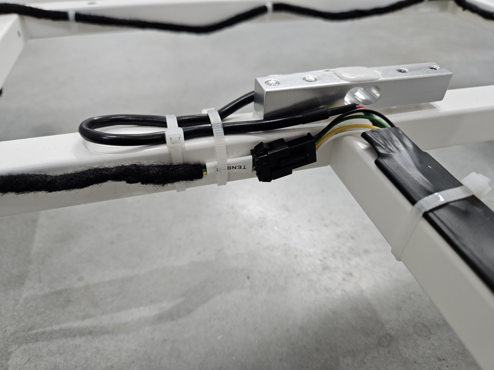
<table border="1" id="bkmrk-unplug-the-sensor" style="border-collapse: collapse; width: 100%; border-width: 1px; border-style: hidden;"><colgroup><col style="width: 50%;"></col><col style="width: 50%;"></col></colgroup><tbody><tr><td>- Unplug the sensor

</td><td>[![20231117_091935.jpg](https://docs.bine.world/uploads/images/gallery/2023-11/scaled-1680-/70ME9Th4eTsJzcgi-20231117-091935.jpg)](https://docs.bine.world/uploads/images/gallery/2023-11/70ME9Th4eTsJzcgi-20231117-091935.jpg)</td></tr></tbody></table>

---

#### **Step 3** Remove zippers

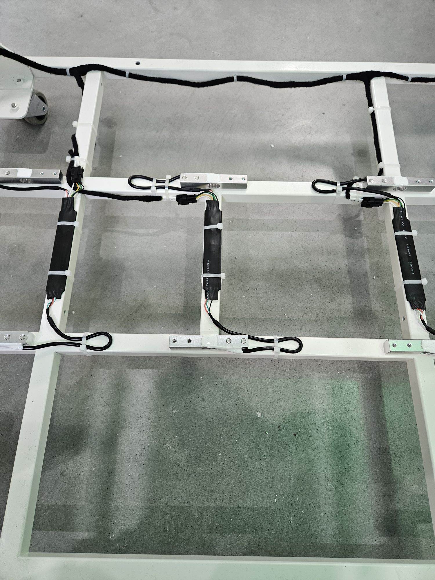
<table border="1" id="bkmrk--2" style="border-collapse: collapse; width: 100%; border-width: 1px; border-style: hidden;"><colgroup><col style="width: 50%;"></col><col style="width: 50%;"></col></colgroup><tbody><tr><td>  
</td><td>[![20231117_091525.jpg](https://docs.bine.world/uploads/images/gallery/2023-11/scaled-1680-/aRcLadXht2N8700Q-20231117-091525.jpg)](https://docs.bine.world/uploads/images/gallery/2023-11/aRcLadXht2N8700Q-20231117-091525.jpg)</td></tr></tbody></table>

---

#### **Step 4** Unscrew sensor form frame

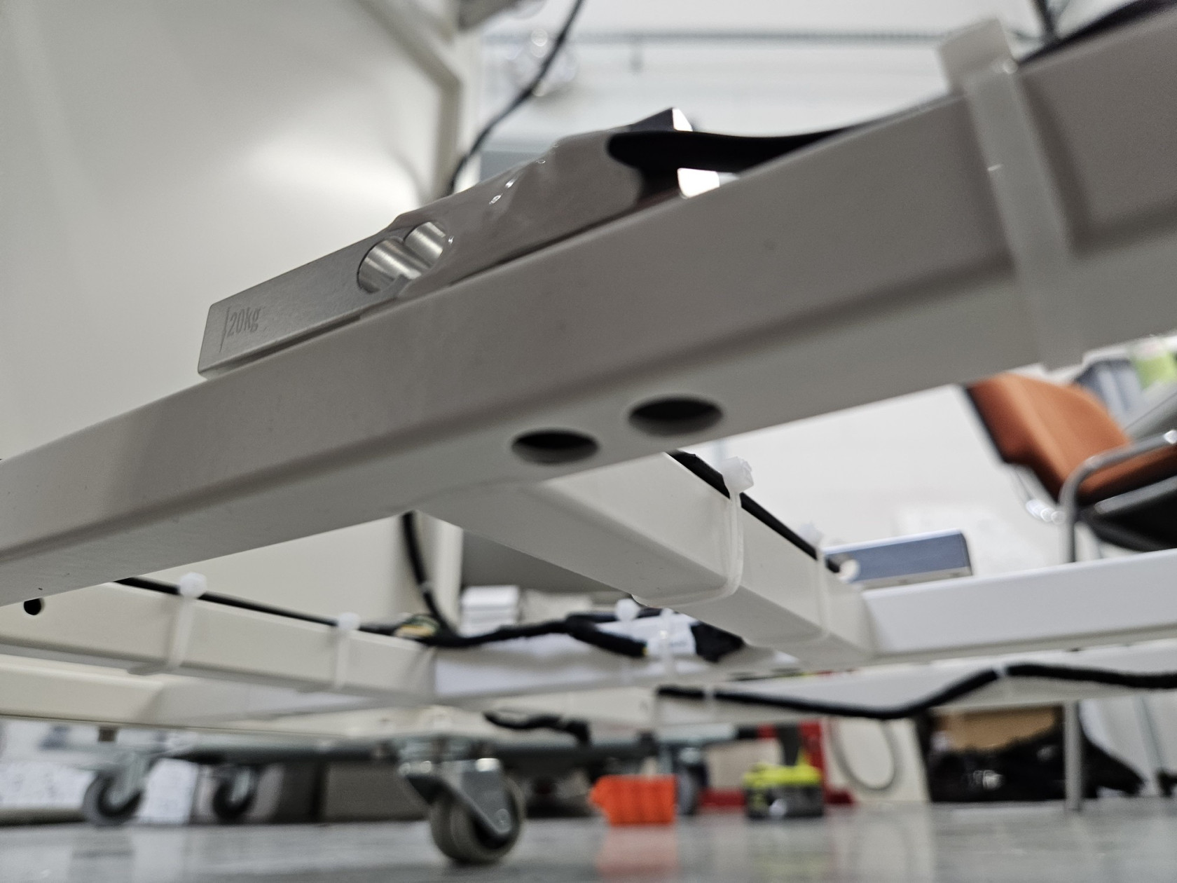
<table border="1" id="bkmrk--8" style="border-collapse: collapse; width: 100%; border-width: 1px; border-style: hidden;"><colgroup><col style="width: 50%;"></col><col style="width: 50%;"></col></colgroup><tbody><tr><td style="border-width: 1px;">- There are two bolt (for each load cell) form bottom (alen key 4)

</td><td style="border-width: 1px;">[![ZeVADu0vXqx2c2nE-20231117-091736.jpg](https://docs.bine.world/uploads/images/gallery/2023-11/scaled-1680-/nzYhjKCmNogtv9pg-zevadu0vxqx2c2ne-20231117-091736.jpg)](https://docs.bine.world/uploads/images/gallery/2023-11/nzYhjKCmNogtv9pg-zevadu0vxqx2c2ne-20231117-091736.jpg)</td></tr><tr><td style="border-width: 1px;"></td><td style="border-width: 1px;">[![uSVs6HyEOUR9hmRp-20231117-091914.jpg](https://docs.bine.world/uploads/images/gallery/2023-11/scaled-1680-/lhANya5U3LgQ7teH-usvs6hyeour9hmrp-20231117-091914.jpg)](https://docs.bine.world/uploads/images/gallery/2023-11/lhANya5U3LgQ7teH-usvs6hyeour9hmrp-20231117-091914.jpg)

</td></tr></tbody></table>

---

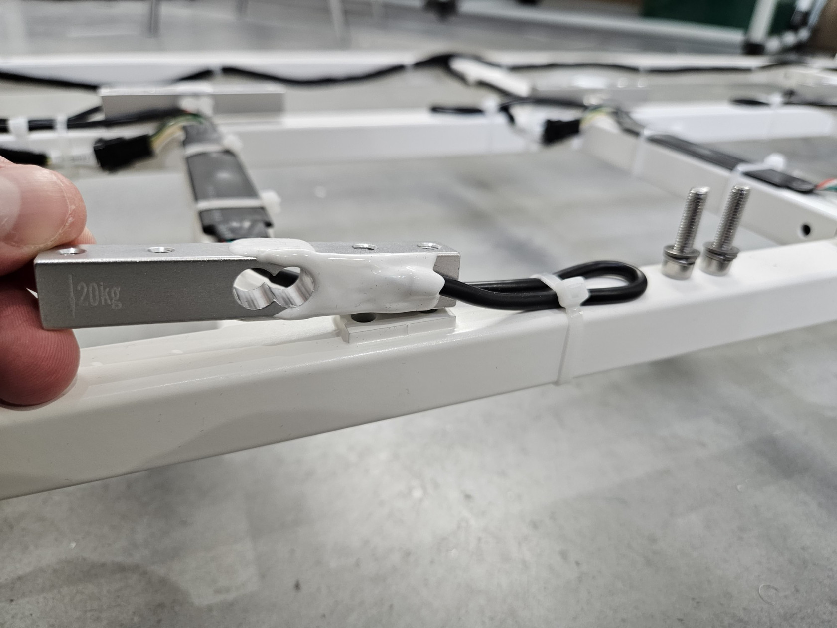
#### **Step 5** Set new sensor

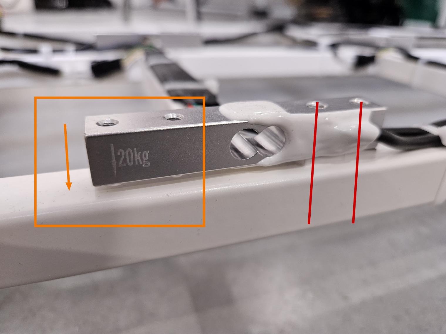
<p class="callout warning">Pay special attention to the direction! The beam has an arrow drawn on it. This arrow should point down and be on the opposite side of the mounting screws to the frame! (see photo below)  
On the front of the device, the arrow should be on the left and on the back on the right.</p>

<table border="1" id="bkmrk-najpierw-u%C5%82%C3%B3%C5%BC-belki-" style="border-collapse: collapse; width: 100%; border-width: 1px; border-style: hidden;"><colgroup><col style="width: 50%;"></col><col style="width: 50%;"></col></colgroup><tbody><tr><td>- first place the beams in their final positions
- screw the first one (closer to the front door)
- then the second one at the back similarly to the description (on the back it is on the other side)

</td><td>[![20231117_0915451.jpg](https://docs.bine.world/uploads/images/gallery/2023-11/scaled-1680-/UbbyQpbq1GIg9jll-20231117-0915451.jpg)](https://docs.bine.world/uploads/images/gallery/2023-11/UbbyQpbq1GIg9jll-20231117-0915451.jpg)</td></tr></tbody></table>

---

#### **Step 6** Secure cable and PCB with zippers

<table border="1" id="bkmrk-asdasd" style="border-collapse: collapse; width: 100%; border-width: 1px; border-style: hidden;"><colgroup><col style="width: 50%;"></col><col style="width: 50%;"></col></colgroup><tbody><tr><td>- 

</td><td>[![20231117_091525.jpg](https://docs.bine.world/uploads/images/gallery/2023-11/scaled-1680-/aRcLadXht2N8700Q-20231117-091525.jpg)](https://docs.bine.world/uploads/images/gallery/2023-11/aRcLadXht2N8700Q-20231117-091525.jpg)</td></tr></tbody></table>

---

#### **Step 7** Plug in a new sensor

<table border="1" id="bkmrk--15" style="border-collapse: collapse; width: 100%; border-width: 1px; border-style: hidden;"><colgroup><col style="width: 50%;"></col><col style="width: 50%;"></col></colgroup><tbody><tr><td>  
</td><td>[![20231117_091935.jpg](https://docs.bine.world/uploads/images/gallery/2023-11/scaled-1680-/70ME9Th4eTsJzcgi-20231117-091935.jpg)](https://docs.bine.world/uploads/images/gallery/2023-11/70ME9Th4eTsJzcgi-20231117-091935.jpg)</td></tr></tbody></table>

---

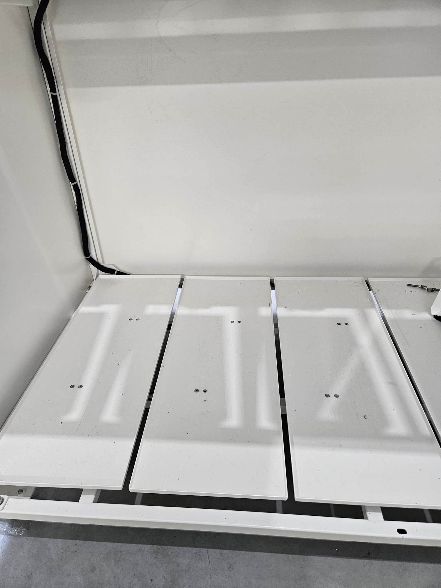
#### **Step 8** Screw flor again

<p class="callout warning">The floor is not symmetrical! Orient it similarly to the others!</p>

<table border="1" id="bkmrk-%C2%A0-5" style="border-collapse: collapse; width: 100%; height: 29.6px; border-width: 1px; border-style: hidden;"><colgroup><col style="width: 50%;"></col><col style="width: 50%;"></col></colgroup><tbody><tr style="height: 29.6px;"><td style="height: 29.6px;"> </td><td style="height: 29.6px;">[![h6WN2VgvyqWfRjB5-1.jpg](https://docs.bine.world/uploads/images/gallery/2023-11/scaled-1680-/00piKditb3Fu7nNE-h6wn2vgvyqwfrjb5-1.jpg)](https://docs.bine.world/uploads/images/gallery/2023-11/00piKditb3Fu7nNE-h6wn2vgvyqwfrjb5-1.jpg)</td></tr></tbody></table>

---

#### **Step 9** Wieght calibration

<p class="callout info">Full calibration is required after load cell replacement. THIS IS A DIFFERENT CALIBRATION THAN ZERO CALIBRATION FROM THE MENU. Right now there is no possible full calibration from user menu.</p>

<p class="callout warning">Calibration consists of 4 stages  
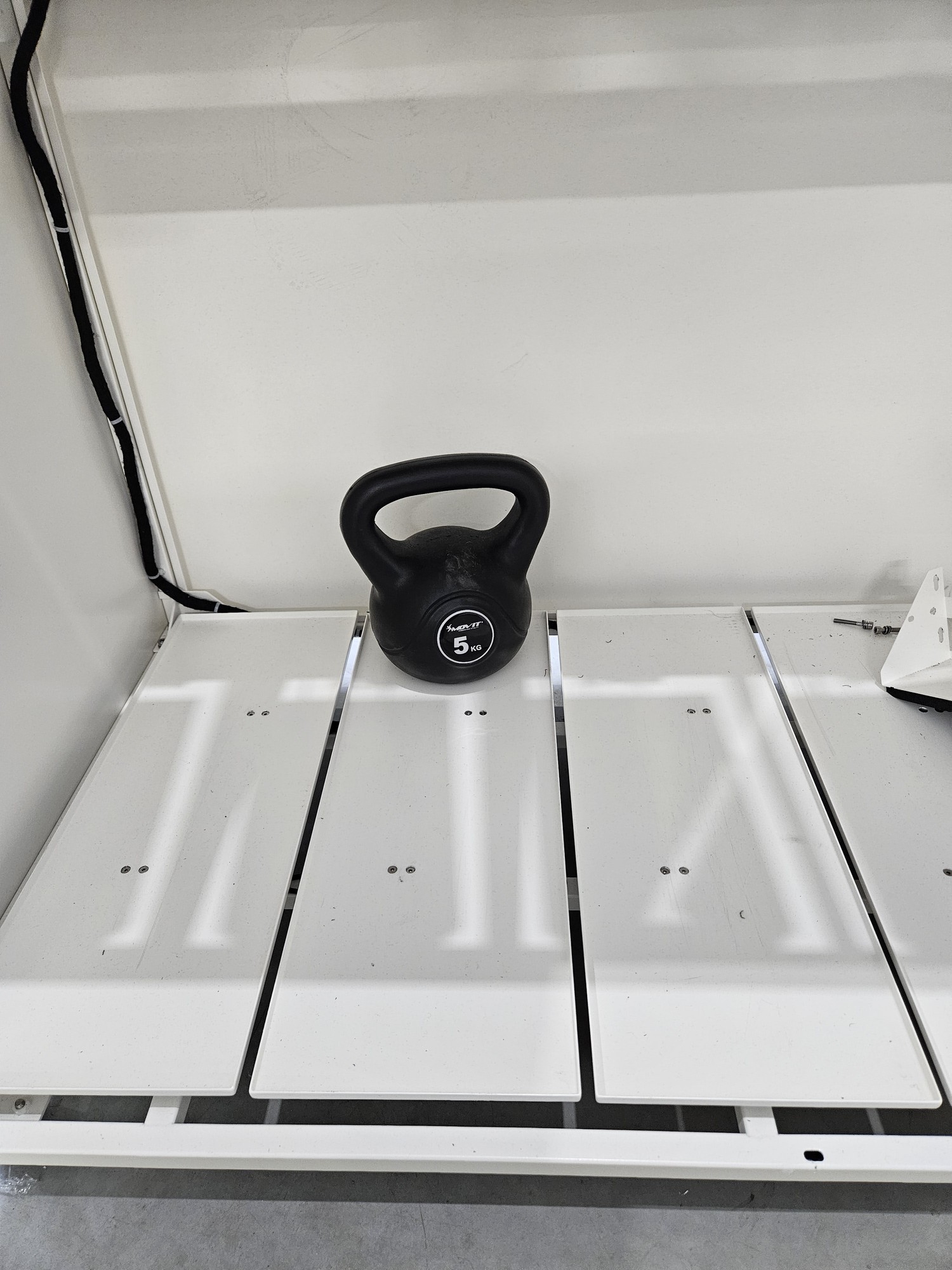
1. empty beam  
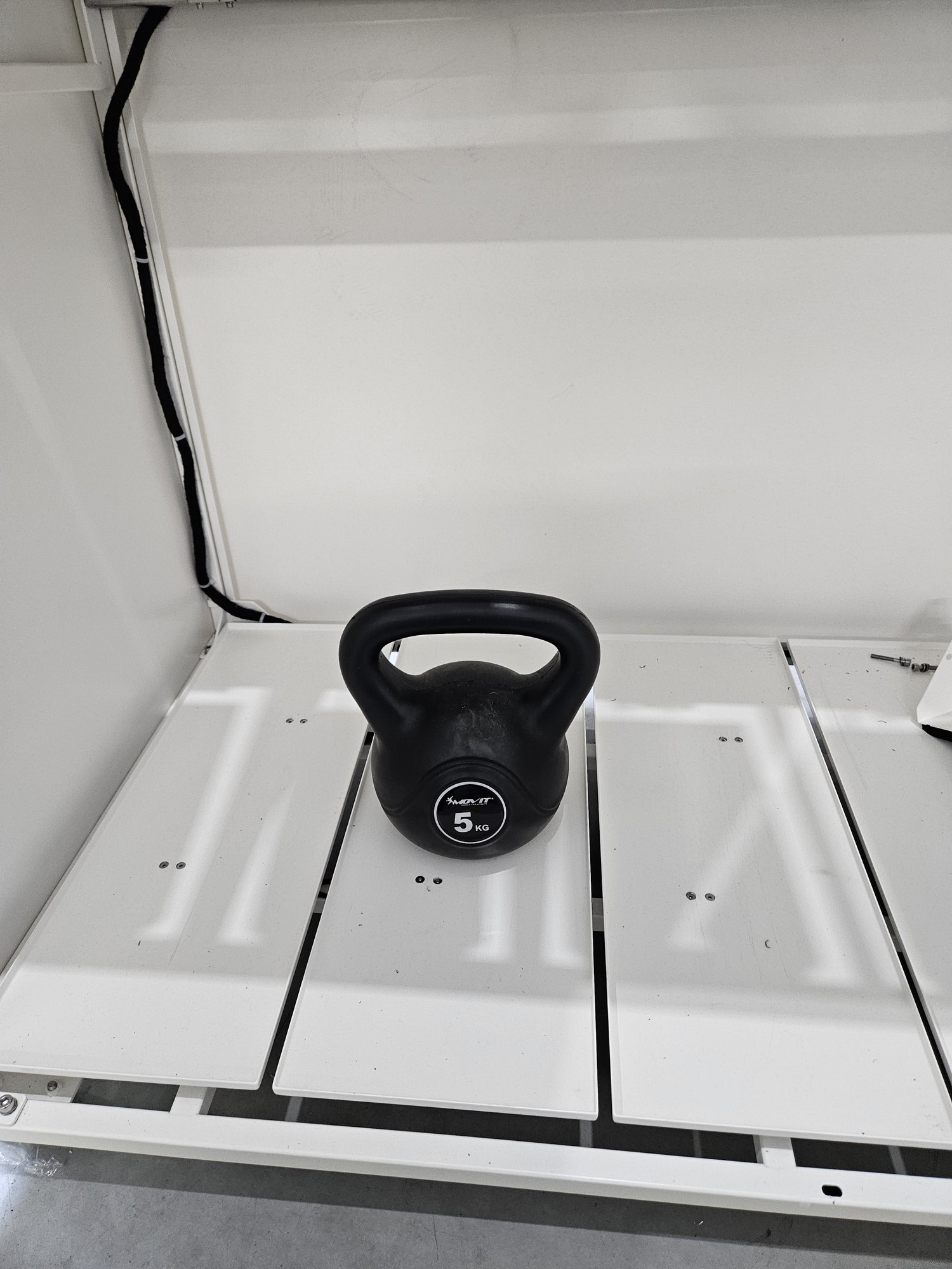
2. load placed at the back  
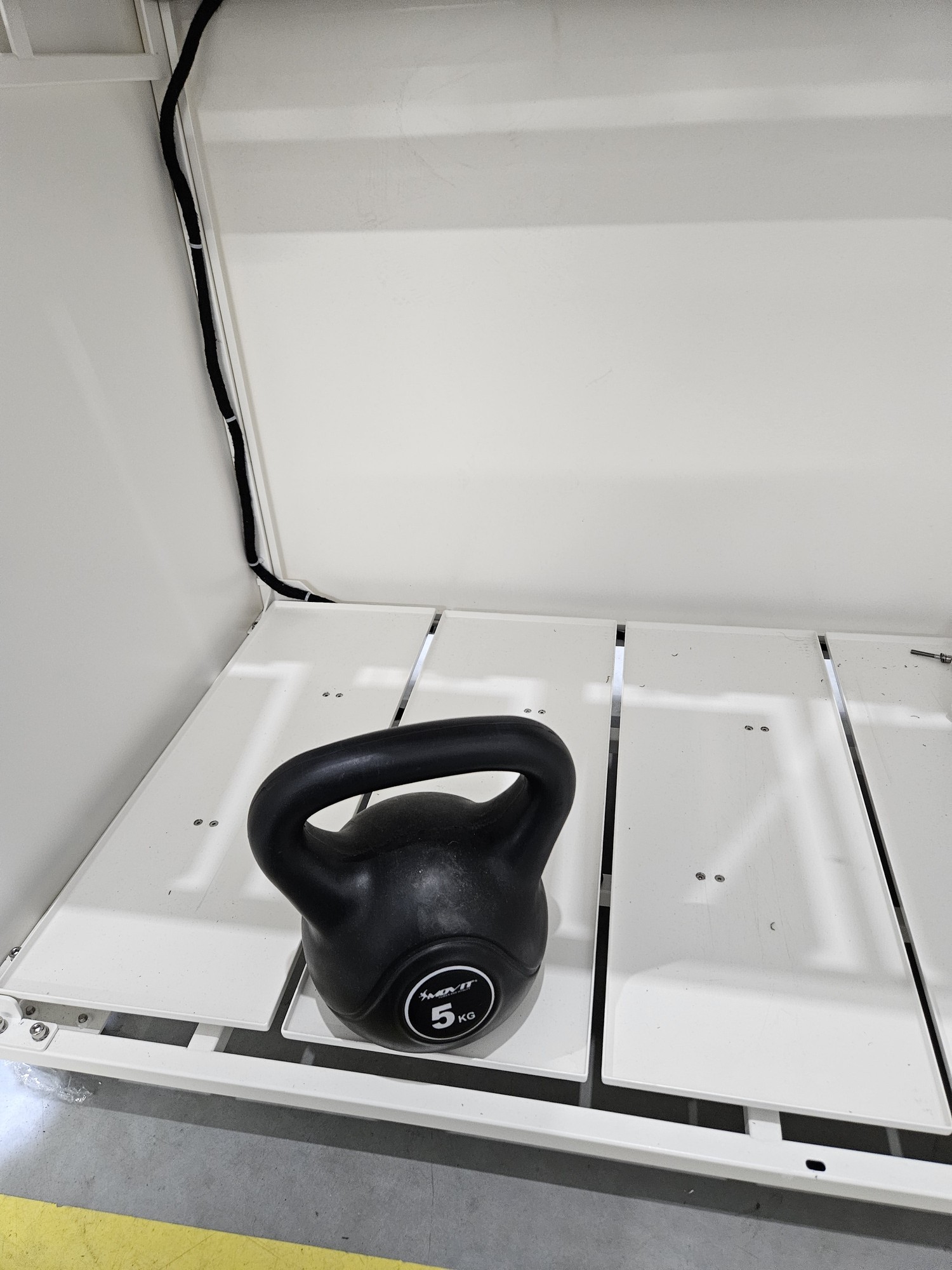
3. load placed in the middle  
4. load placed at the front</p>

<table border="1" id="bkmrk--19" style="border-collapse: collapse; width: 100%; border-width: 1px; border-style: hidden;"><colgroup><col style="width: 50%;"></col><col style="width: 50%;"></col></colgroup><tbody><tr><td>  
</td><td>[![pusta.jpg](https://docs.bine.world/uploads/images/gallery/2023-11/scaled-1680-/hhegjpQ4Ss5lIuOk-pusta.jpg)](https://docs.bine.world/uploads/images/gallery/2023-11/hhegjpQ4Ss5lIuOk-pusta.jpg)</td></tr><tr><td>  
</td><td>[![kalibracja tyl.jpg](https://docs.bine.world/uploads/images/gallery/2023-11/scaled-1680-/gpbQO7818iTjEneq-kalibracja-tyl.jpg)](https://docs.bine.world/uploads/images/gallery/2023-11/gpbQO7818iTjEneq-kalibracja-tyl.jpg)</td></tr><tr><td>  
</td><td>[![kalibracja srodek.jpg](https://docs.bine.world/uploads/images/gallery/2023-11/scaled-1680-/nwief27SWeFU7Pp7-kalibracja-srodek.jpg)](https://docs.bine.world/uploads/images/gallery/2023-11/nwief27SWeFU7Pp7-kalibracja-srodek.jpg)</td></tr><tr><td>  
</td><td>[![kalibracja przod.jpg](https://docs.bine.world/uploads/images/gallery/2023-11/scaled-1680-/aimtQpKXbQ6kNH3i-kalibracja-przod.jpg)](https://docs.bine.world/uploads/images/gallery/2023-11/aimtQpKXbQ6kNH3i-kalibracja-przod.jpg)</td></tr></tbody></table>

# Replace motors mechanism Smartb

<table border="1" id="bkmrk-czasami-co%C5%9B-si%C4%99-pops" style="border-collapse: collapse; width: 100%; border-width: 1px; border-style: hidden;"><colgroup><col style="width: 50%;"></col><col style="width: 50%;"></col></colgroup><tbody><tr><td style="border-width: 1px;">In this document you will find a description how to replace the throw flaps motors system in the Smartb

</td><td style="border-width: 1px;">You will need:

- a new set of motors mechanism
- a set of allen keys
- cross screwdriver

</td></tr></tbody></table>

<p class="callout danger">Before replacing disconnect device from the power supply!</p>

<p class="callout info">With practice, some points can be omitted, but the simplest path will be described here</p>

---

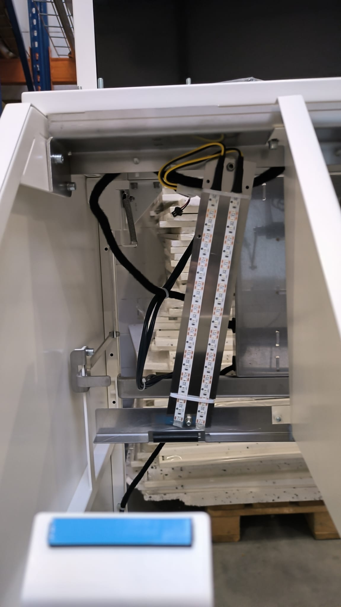
#### **Step 1** Remove metal cover with shape 

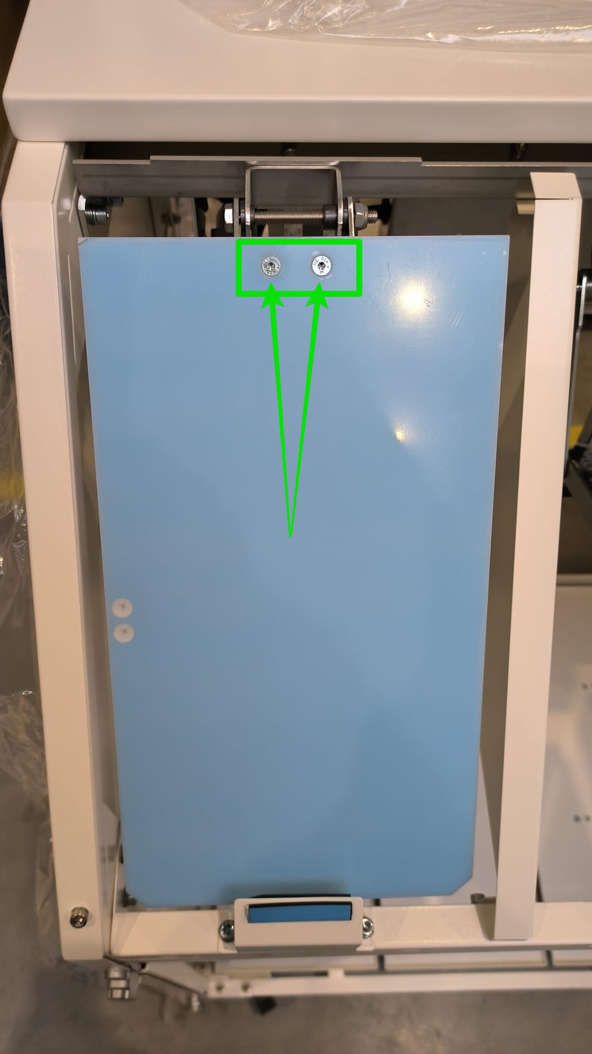
<table border="1" id="bkmrk-the-top-floor-is-bol" style="border-collapse: collapse; width: 100%; border-width: 1px; border-style: hidden;"><colgroup><col style="width: 50%;"></col><col style="width: 50%;"></col></colgroup><tbody><tr><td>- Open door
- Unscrew metal cover

</td><td>[![WhatsApp Image 2024-01-25 at 09.55.48.jpeg](https://docs.bine.world/uploads/images/gallery/2024-01/scaled-1680-/wEMLORwEwFn5f1JH-whatsapp-image-2024-01-25-at-09-55-48.jpeg)](https://docs.bine.world/uploads/images/gallery/2024-01/wEMLORwEwFn5f1JH-whatsapp-image-2024-01-25-at-09-55-48.jpeg)[![WhatsApp Image 2024-01-25 at 09.56.02.jpeg](https://docs.bine.world/uploads/images/gallery/2024-01/scaled-1680-/c5ZrlL7xve5Jvc62-whatsapp-image-2024-01-25-at-09-56-02.jpeg)](https://docs.bine.world/uploads/images/gallery/2024-01/c5ZrlL7xve5Jvc62-whatsapp-image-2024-01-25-at-09-56-02.jpeg)</td></tr></tbody></table>

---

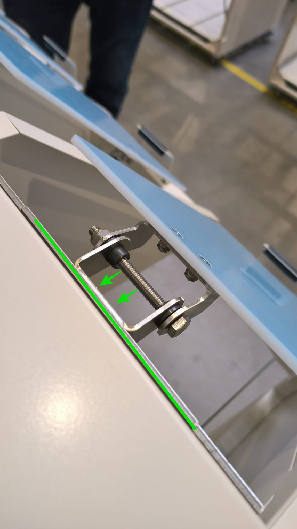
#### **Step 2** Unscrew plastic flaps (optional)

<table border="1" id="bkmrk-unplug-the-sensor" style="border-collapse: collapse; width: 100%; border-width: 1px; border-style: hidden;"><colgroup><col style="width: 50%;"></col><col style="width: 50%;"></col></colgroup><tbody><tr><td>- this is just to have easier access to the motor plug and screw. Is not always necessary
- <span style="color: rgb(53, 152, 219);">**Depending on the hardware version, may be blind rivet nuts or a separate nut**</span>

</td><td>[![WhatsApp Image 2024-01-25 at 10.41.45.jpeg](https://docs.bine.world/uploads/images/gallery/2024-01/scaled-1680-/9BedsVxDQoOdH130-whatsapp-image-2024-01-25-at-10-41-45.jpeg)](https://docs.bine.world/uploads/images/gallery/2024-01/9BedsVxDQoOdH130-whatsapp-image-2024-01-25-at-10-41-45.jpeg)![WhatsApp Image 2024-01-25 at 09.56.26.jpeg](https://docs.bine.world/uploads/images/gallery/2024-01/scaled-1680-/CzLxzWZ2M5dzywct-whatsapp-image-2024-01-25-at-09-56-26.jpeg)</td></tr></tbody></table>
---

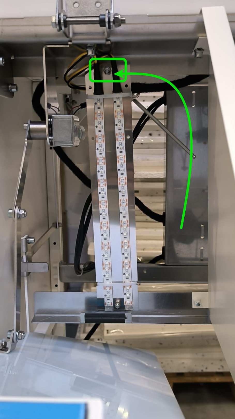
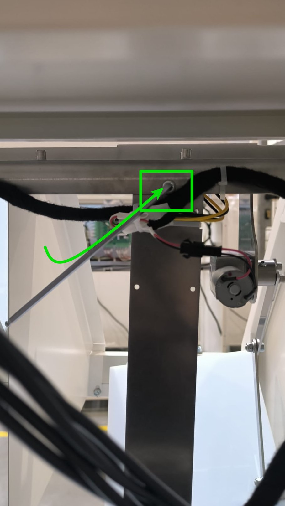
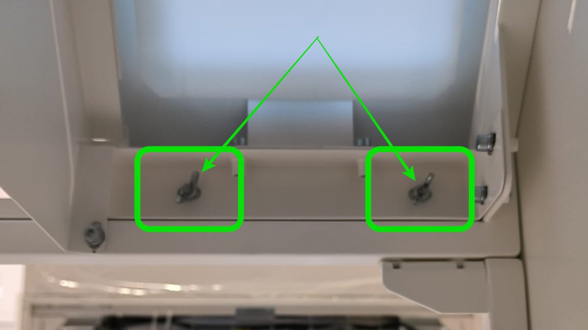
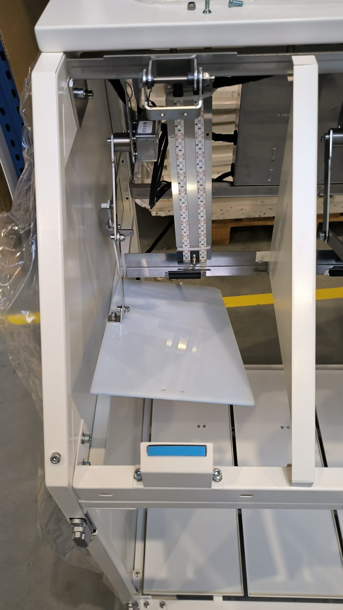
#### **Step 3** Unscrew led holder (optional)

<table border="1" id="bkmrk--2" style="border-collapse: collapse; width: 100%; border-width: 1px; border-style: hidden;"><colgroup><col style="width: 50%;"></col><col style="width: 50%;"></col></colgroup><tbody><tr><td>- this is just to have easier access to the motor plug and screw. Is not always necessary
- <span style="color: rgb(53, 152, 219);">**Depending on the hardware version, the bolt may be from the front or rear**</span>

</td><td>[![WhatsApp Image 2024-01-25 at 09.56.52.jpeg](https://docs.bine.world/uploads/images/gallery/2024-01/scaled-1680-/efqAuNxn2bp39d7o-whatsapp-image-2024-01-25-at-09-56-52.jpeg)](https://docs.bine.world/uploads/images/gallery/2024-01/efqAuNxn2bp39d7o-whatsapp-image-2024-01-25-at-09-56-52.jpeg)</td></tr><tr><td>  
</td><td>[![WhatsApp Image 2024-01-25 at 11.05.23.jpeg](https://docs.bine.world/uploads/images/gallery/2024-01/scaled-1680-/DHwY7SQSuhwQ7w2z-whatsapp-image-2024-01-25-at-11-05-23.jpeg)](https://docs.bine.world/uploads/images/gallery/2024-01/DHwY7SQSuhwQ7w2z-whatsapp-image-2024-01-25-at-11-05-23.jpeg)  
</td></tr></tbody></table>

---

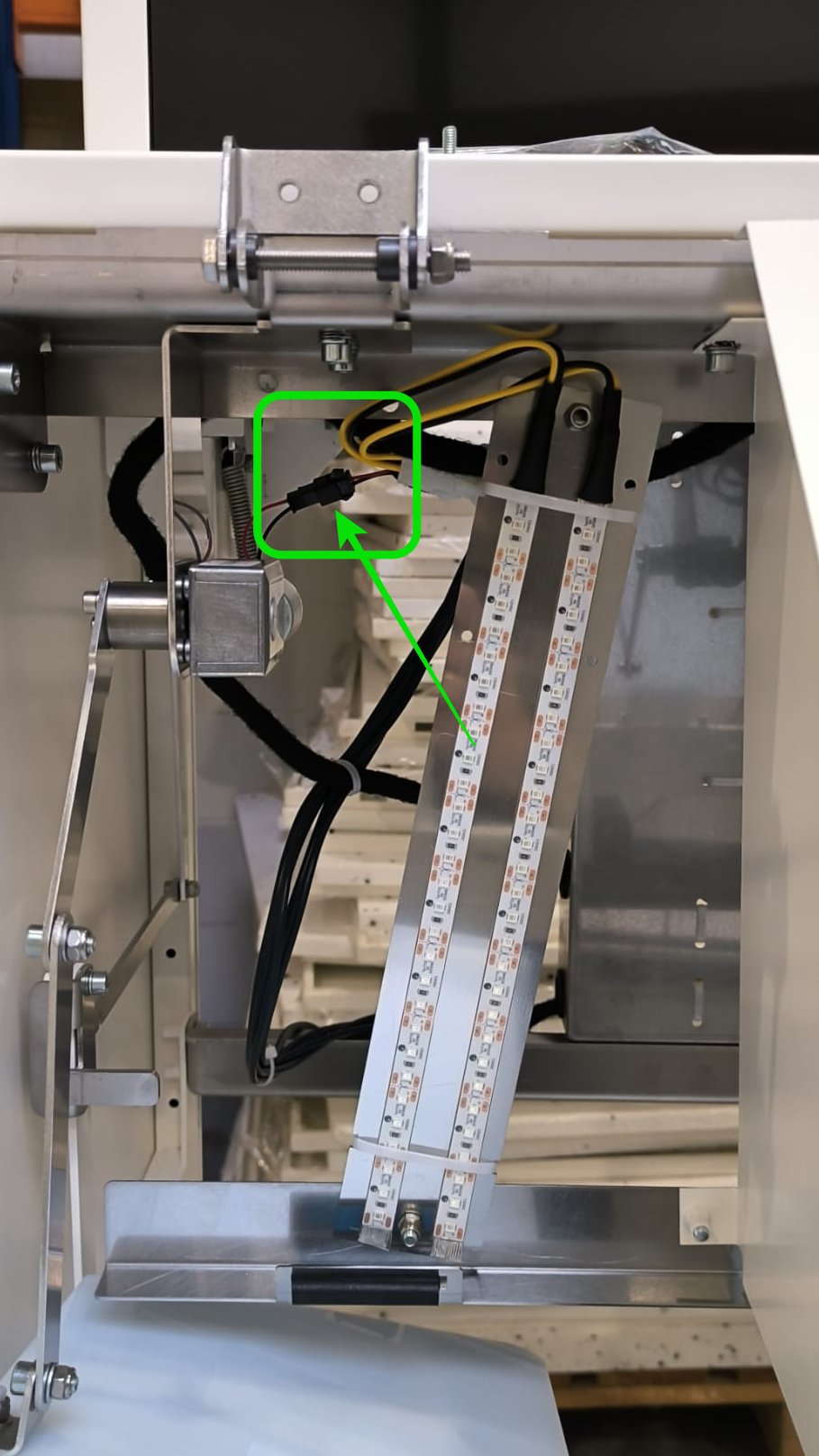
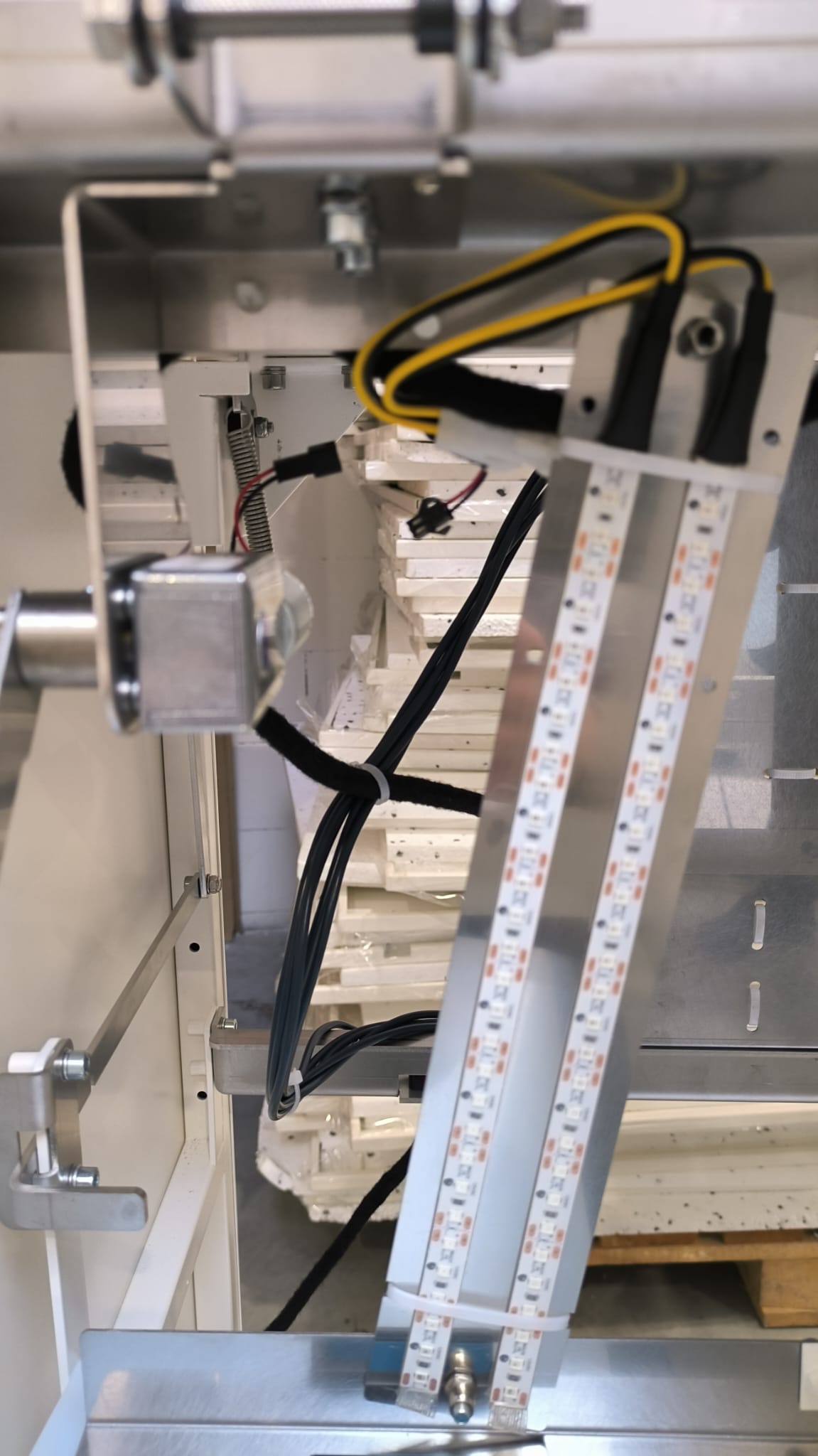
#### **Step 4** Unplug motor cable

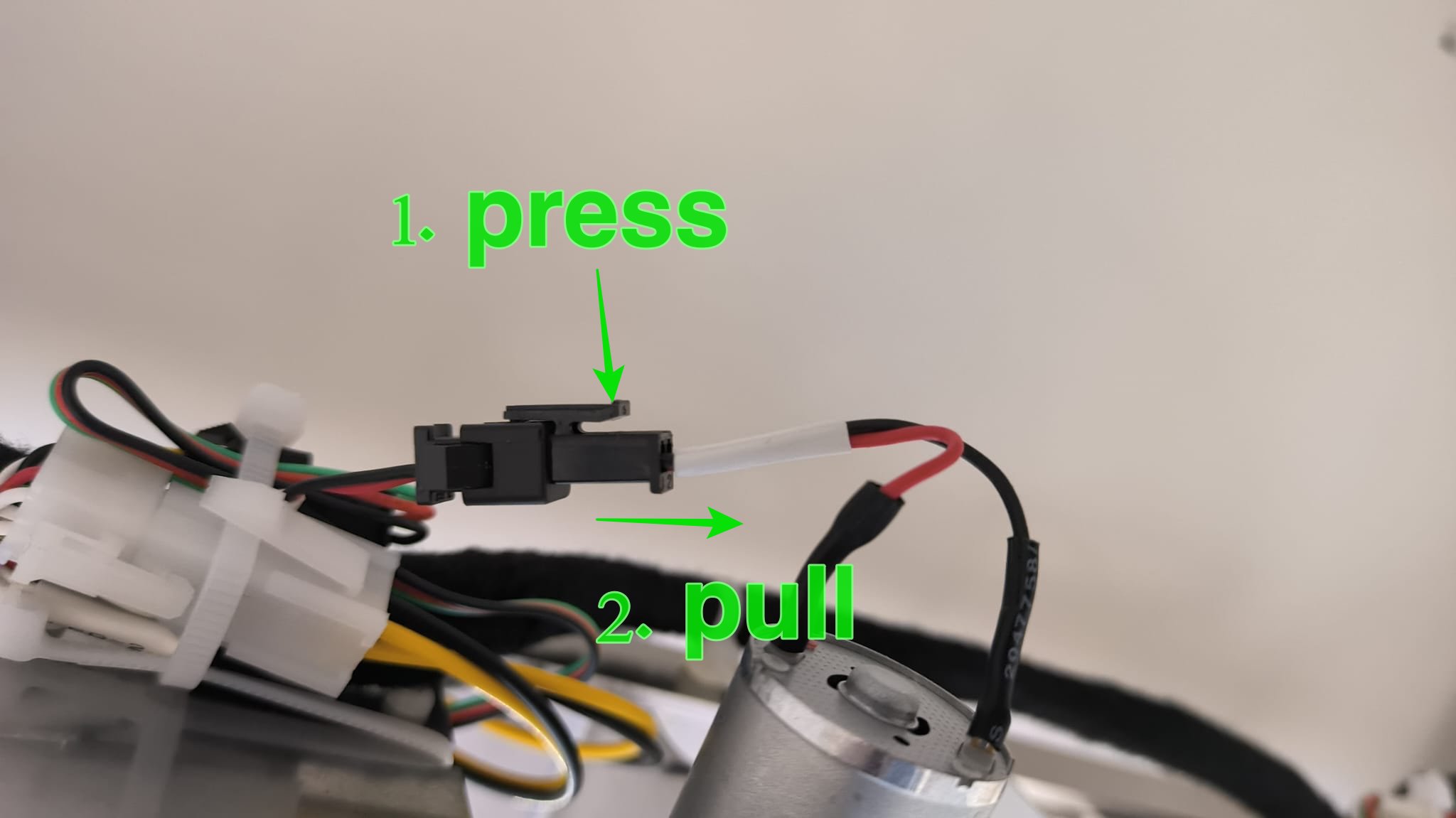
<table border="1" id="bkmrk--8" style="border-collapse: collapse; width: 100%; border-width: 1px; border-style: hidden;"><colgroup><col style="width: 50%;"></col><col style="width: 50%;"></col></colgroup><tbody><tr><td style="border-width: 1px;">- there is only one two-pin plug with a red and black cable

</td><td style="border-width: 1px;">[![WhatsApp Image 2024-01-25 at 09.57.04.jpeg](https://docs.bine.world/uploads/images/gallery/2024-01/scaled-1680-/wasFKjvBVNhyFzH4-whatsapp-image-2024-01-25-at-09-57-04.jpeg)](https://docs.bine.world/uploads/images/gallery/2024-01/wasFKjvBVNhyFzH4-whatsapp-image-2024-01-25-at-09-57-04.jpeg)</td></tr><tr><td style="border-width: 1px;"><p class="callout warning">Never pull the cables, only the plastic connector!</p>

</td><td style="border-width: 1px;">[![WhatsApp Image 2024-01-25 at 10.03.45 (2).jpeg](https://docs.bine.world/uploads/images/gallery/2024-01/1I8Nr7owi3qwO82A-whatsapp-image-2024-01-25-at-10-03-45-2.jpeg)](https://docs.bine.world/uploads/images/gallery/2024-01/1I8Nr7owi3qwO82A-whatsapp-image-2024-01-25-at-10-03-45-2.jpeg)

</td></tr><tr><td style="border-width: 1px;"></td><td style="border-width: 1px;">[![WhatsApp Image 2024-01-25 at 09.57.33.jpeg](https://docs.bine.world/uploads/images/gallery/2024-01/scaled-1680-/LihvrbbPfP6qn4xy-whatsapp-image-2024-01-25-at-09-57-33.jpeg)](https://docs.bine.world/uploads/images/gallery/2024-01/LihvrbbPfP6qn4xy-whatsapp-image-2024-01-25-at-09-57-33.jpeg)

</td></tr></tbody></table>

---

#### **Step 5** Unscrew motor mechanism

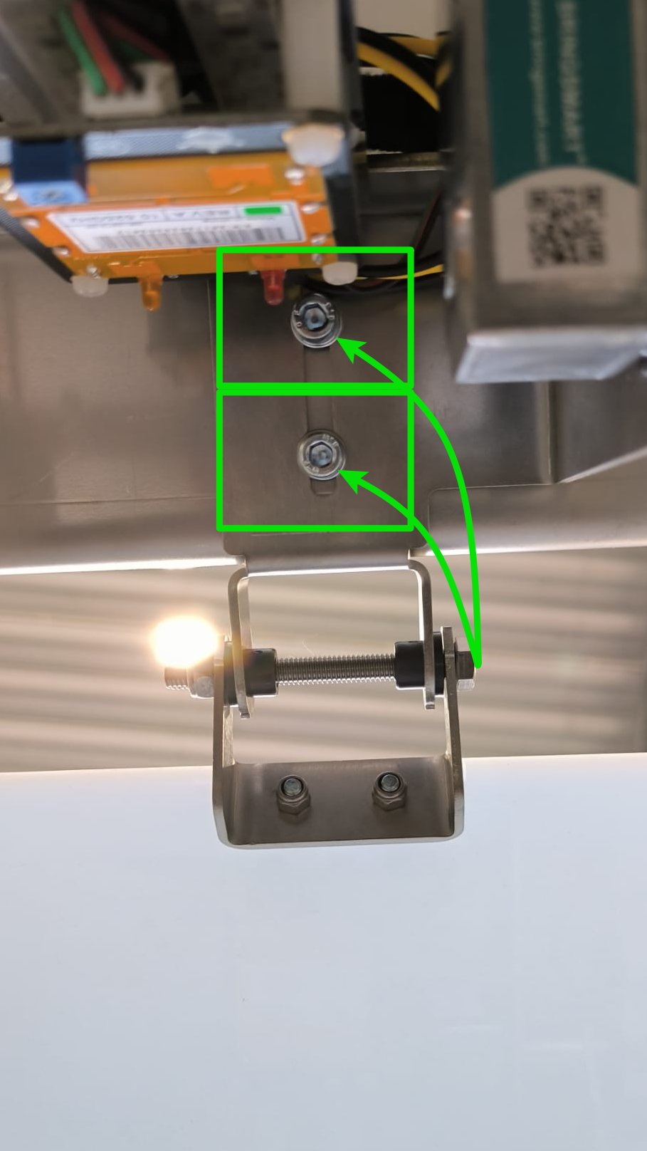
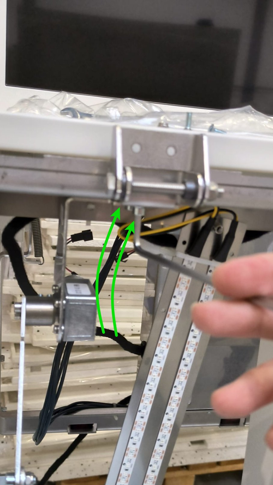
<table border="1" id="bkmrk-najpierw-u%C5%82%C3%B3%C5%BC-belki-" style="border-collapse: collapse; width: 100%; border-width: 1px; border-style: hidden; height: 839.008px;"><colgroup><col style="width: 50%;"></col><col style="width: 50%;"></col></colgroup><tbody><tr style="height: 416.555px;"><td style="height: 416.555px;">- there are two Allen screws holding the entire mechanism

</td><td style="height: 416.555px;">[![WhatsApp Image 2024-01-25 at 10.03.46.jpeg](https://docs.bine.world/uploads/images/gallery/2024-01/scaled-1680-/Qzt9pbdOZTh53gqp-whatsapp-image-2024-01-25-at-10-03-46.jpeg)](https://docs.bine.world/uploads/images/gallery/2024-01/Qzt9pbdOZTh53gqp-whatsapp-image-2024-01-25-at-10-03-46.jpeg)</td></tr><tr style="height: 422.453px;"><td style="height: 422.453px;">  
</td><td style="height: 422.453px;">[![WhatsApp Image 2024-01-25 at 09.58.00.jpeg](https://docs.bine.world/uploads/images/gallery/2024-01/scaled-1680-/XZeuyrJmxDszB5jl-whatsapp-image-2024-01-25-at-09-58-00.jpeg)](https://docs.bine.world/uploads/images/gallery/2024-01/XZeuyrJmxDszB5jl-whatsapp-image-2024-01-25-at-09-58-00.jpeg)</td></tr></tbody></table>

---

#### **Step 6** Now you can replace with new mechanism and assembly with opposite direction of the points

<table border="1" id="bkmrk-asdasd" style="border-collapse: collapse; width: 100%; border-width: 1px; border-style: hidden;"><colgroup><col style="width: 50%;"></col><col style="width: 50%;"></col></colgroup><tbody><tr><td></td><td>[![WhatsApp Image 2024-01-25 at 09.58.25.jpeg](https://docs.bine.world/uploads/images/gallery/2024-01/scaled-1680-/pGZ7gKHw5S5j7JnV-whatsapp-image-2024-01-25-at-09-58-25.jpeg)](https://docs.bine.world/uploads/images/gallery/2024-01/pGZ7gKHw5S5j7JnV-whatsapp-image-2024-01-25-at-09-58-25.jpeg)</td></tr><tr><td>- <span style="color: rgb(53, 152, 219);">**when installing the new mechanism, make sure that the parts fit together as in the photo**</span>

</td><td>[![WhatsApp Image 2024-01-25 at 09.56.13.jpeg](https://docs.bine.world/uploads/images/gallery/2024-01/scaled-1680-/dJ04YF4RzECGTTbK-whatsapp-image-2024-01-25-at-09-56-13.jpeg)](https://docs.bine.world/uploads/images/gallery/2024-01/dJ04YF4RzECGTTbK-whatsapp-image-2024-01-25-at-09-56-13.jpeg)</td></tr></tbody></table>

#### Checklist after replace:

- [ ] no screws remain
- [ ] motor work properly on full range in proper direction
- [ ] LEDs works OK
- [ ] person detect system works OK (on bin 2 and 4)

# Smartb motors - how it works

&lt;Do przeredagowania i translacji&gt;

Sterowanie silnikami w smartb bazuje na pomiarze prądu i czasach ruchu. Nie ma w tym układzie krańcówek położenia skrajnego.

Działa to tak, że logika wysterowuje ruch silnika w zadanym kierunku i czeka aż na silniku wystąpi pomiar prądu powyżej **1A** (tzn, że coś blokuje dalszy ruch silnika, albo jest to odbojnik skrajny w urządzeniu albo coś innego)

Dodatkowo na początku ruchu uruchamiany jest timer który odlicza do **1s**, jeżeli silnik nie osiągnie prądu powyżej **1A** w czasie krótszym niż **1s** to jest emitowy błąd **TIMEOUT (S003).** Źródłem braku prądu w czasie 1s może być awaria silnika lub silnik nie jest podłączony.

Zwykle normalny ruch silnika trwa ok. **600ms**.

Jeżeli silnik osiągnie prąd **1A** w czasie krótszym niż **450ms** to zwykle znaczy, ze coś blokuje jego ruch. Jeżeli taki stan (osiągnięcie prądu poniżej 450ms) wystąpi **3x** pod rząd to emituje błąd **UNDERTIME (S002)**

Po wystąpieniu błędu **TIMEOUT** lub **UNDERTIME** silnik zatrzymuje się i LED świeci się na żółto.

<p class="callout info">Co ważne, po wejściu w tryb serwisowy wszystkie silniki kasują swoją flagę o błędzie i próbują wykonać ruch ponownie wg. w/w opisu.</p>