Device
- Unboxing the device
- First launch
- Installation of external screen
- Access to the inner bins
- Cardboard bins
- How to open the top cover
- SmartB
- The touch screen for customers
Unboxing the device
Device version: every
VIDEO TUTORIAL
DESCRIPTION
After receiving the device it is important to check if the device was handled properly during the transportation. First, please check the tilt sensor placed on the box. If the metal balls are indicating “start” position it means that the device was carried in the right position. However if the metal balls inside are placed in some other position, please take a picture of this and contact us. This is also very important documentation in case you would like to handle the official complaint to the delivery company.
Check if the box is not broken or destroyed. If you see any damages or anything that seems odd, contact us and we will help.

To open the box you will have to use a special tool, which is attached to the box. Start with the top cover because this part will be used as a ramp to safely take the device out of the pallet.
After the top cover, take off the narrow side and then the wider side of the box. Cut the straps which hold the device to the pallet, unlock the wheels by pushing the triggers up and carefully push the device out of the ramp. Disassemble the rest of the box.
Unwrap the device from the securing tape and check if the branding was not damaged during the transportation.

Open the front cover by pulling it and take the inner bins out of the casing just to make sure that they will be placed in the right position. In the first bin you will find a small box with the power cable, manuals and other objects according to your order. Put the bins inside the device and close the front cover.
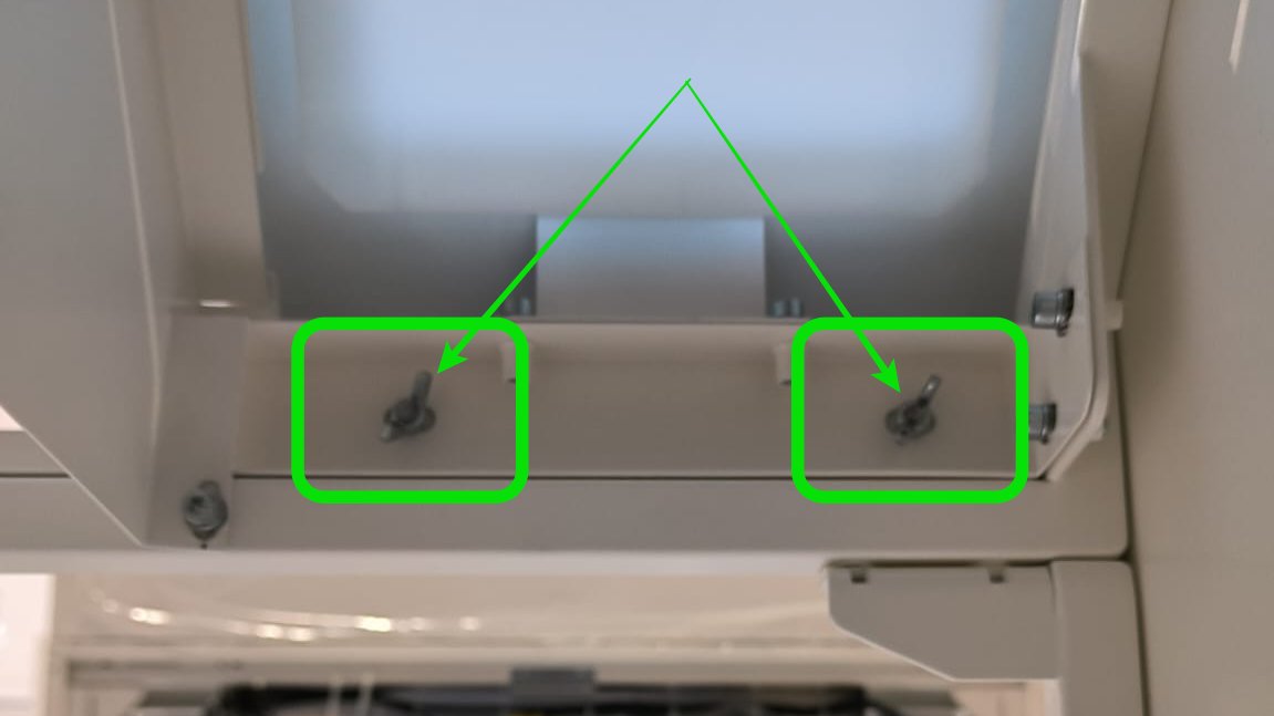
Now open the top cover, in order to unlock it you have to twist the bolts which are placed inside on both sides of the device.
After you open the top cover check if the trolley with the recognition chamber is placed below the opening, above the second bin. If the trolley is in some other position, contact us and we will take additional steps to check if the device is ok. If everything is alright, you can close the top cover and lock it with the bolts.
Next step is the installation.
First launch
Device version: every 4.x.x
VIDEO TUTORIAL
DESCRIPTION
After taking the device out of the box it is ready to be launched. First open the box which was placed in the first inner bin. Inside there is a power cable. The plug is placed on the back of the device in the bottom left corner. After you plug the cable to the device you can connect it to the power source. Next step is to press the switch on the bottom and then press the top button. The touch screen on the top cover should launch and display a progress bar, this process should take around 3-4 minutes.
During the launching the device will load the software, calibrate some inner components and check if inner bins are inside in the right position. If there are no notifications about an error on the touch screen, the device is almost ready to be used.
The device requires connection with the internet. If you are going to use a GSM modem which is placed inside, there is no action needed. The device will connect itself.

If you want to connect the device with WiFi you have to enter the menu by pressing the button in the right top corner and enter “Connection” settings . Enter the details required to connect and accept.

The interface is English by default, but if you want to change the language just enter the MENU >> SETTINGS >> LANGUAGE.
Installation of external screen
Device version: every 4.x.x
VIDEO TUTORIAL
DESCRIPTION
After unwrapping the device, unlock the fixtures which are placed on the bottom of the screen on each side of the screen. It requires unscrewing the safety screws. Push the screen to the vertical position and close the safety locks. This is a very important step so please double check if you close the locks. They are placed inside the device, one on the left and one on the right side. You have to hook the clips on the safety bolt.

Access to the inner bins
Device version: every
VIDEO TUTORIAL
DESCRIPTION
If you want to get access to the inner bins and your device is equipped with the lock you will need a special key which was attached to the device when you received it. Simply open the front cover with the key.
Open the front cover by pulling it up. Inside you will find 4 inner bins, each of them is monitored with a fill level sensor so it is important to place them inside in a proper position. There is a limit switch which indicates where the bin should be placed. If the bin is standing crookedly, take it out and put it back again. To take the bin out of the casing you have to grab the hand grip and pull it a bit up and slowly take the bin out.

WE DO NOT RECOMMEND using plastic rubbish bags because they disturb the work of the fill level sensors and the device might communicate false fill levels.
When you finish replacing or emptying the inner bins just close the front cover and check if there is no error on the screen.
Cardboard bins
Device version: every
VIDEO TUTORIAL
DESCRIPTION
Cardboard inner bins as a standard will arrive to you unfolded. On the video we show you how to fold it, so we recommend you to watch it.
The complete cardboard bin set consist of a bin, a lid and two sides.
To fold the bin you need to take the biggest cardboard and fold the sides of the box. Then you need to fold the bottom. But please, remember to do that in the correct order - first the part with the cutting in the middle, then the sides and at the end fold the last part by pushing it under the previous pieces.
To fold the lid you need to take the cardboard with two cut circles in the center. First, fold the shorter edges, then fold the longer ones and please make sure that the blockages are in the right place.
The last thing you need to do is to place two remaining sides inside the bin and put the bins into the device.
There is also a special stopper adjusted to the bin, so take a closer look while placing the bins inside. It helps to place the bin in a proper position.
How to open the top cover
Device version: every
VIDEO TUTORIAL
DESCRIPTION
Such operation may be needed, for example, during a service action or when an object is stuck in the device.
The upper flap of the device has a locking system that protects the device against unauthorized interference.
To unlock the top cover, turn the locking bolts located inside the device on each side. Now you can open the top cover freely.

Remember, however, that when you want to close it, you have to turn the bolts to the locking position and only then you can close the cover with the certainty that it will be locked again.
One more thing! For safety reasons, our device is equipped with limit switches to determine whether it is open or closed. When the top cover is open, neither engine in the machine will start running.
SmartB
Replace weight sensor
|
In this document you will find a description how to replace the weight sensor in the Smartb
|
You will need:
|
Before replacing disconnect device from the power supply!
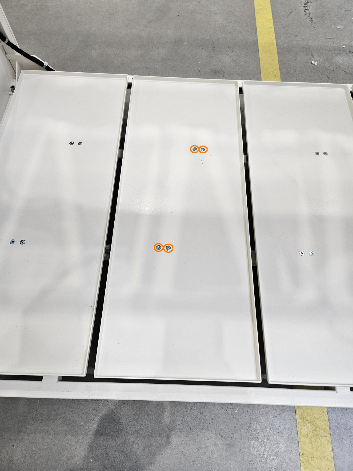
Step 1 Unscrew the top floor
|
 |
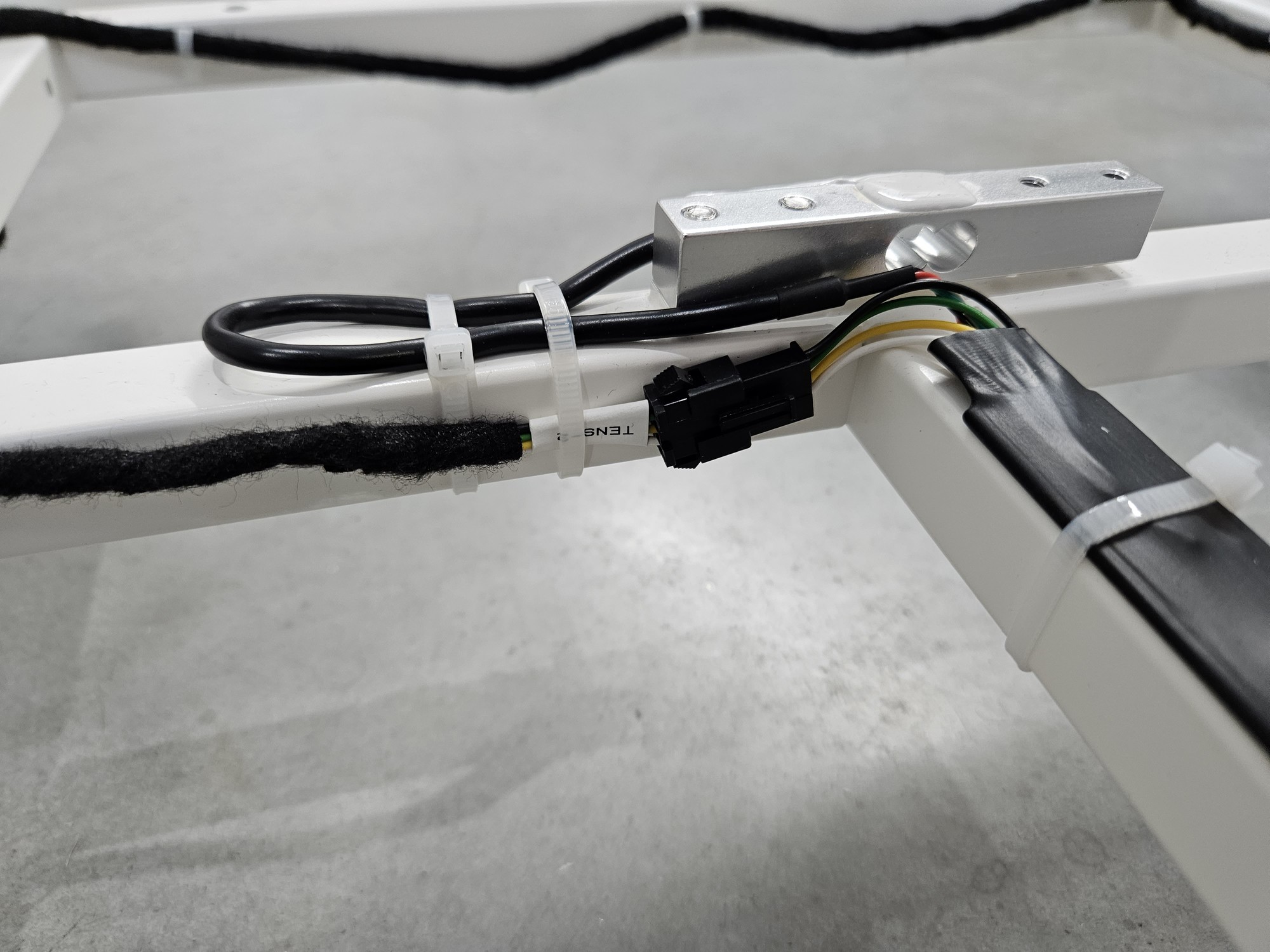
Step 2 Unplug the sensor
|
 |
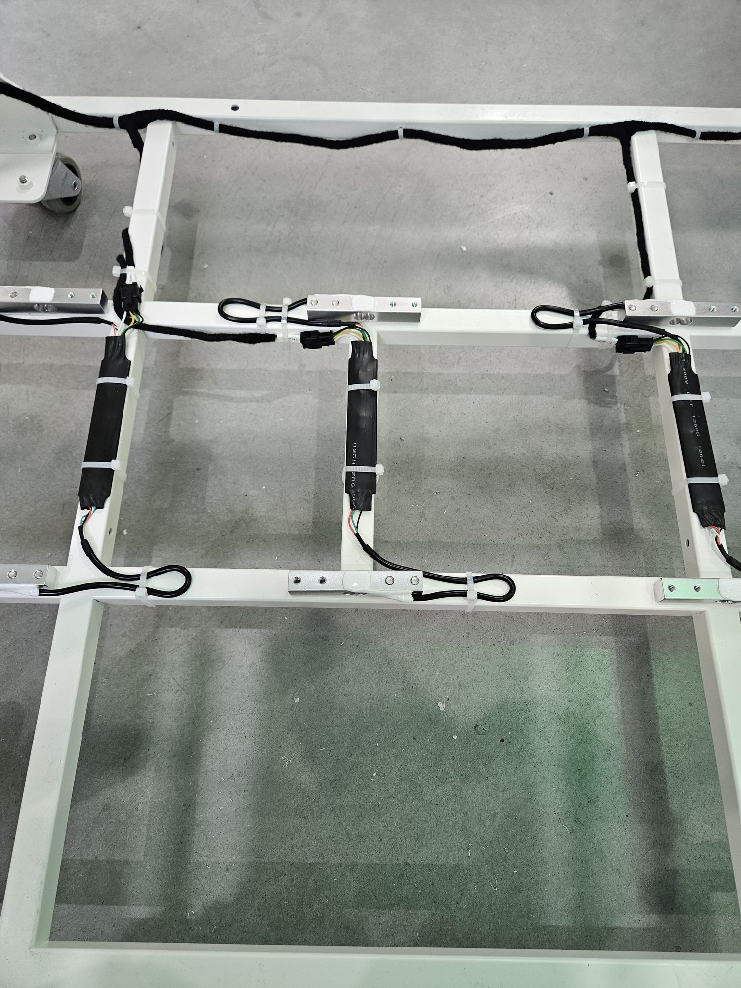
Step 3 Remove zippers
 |
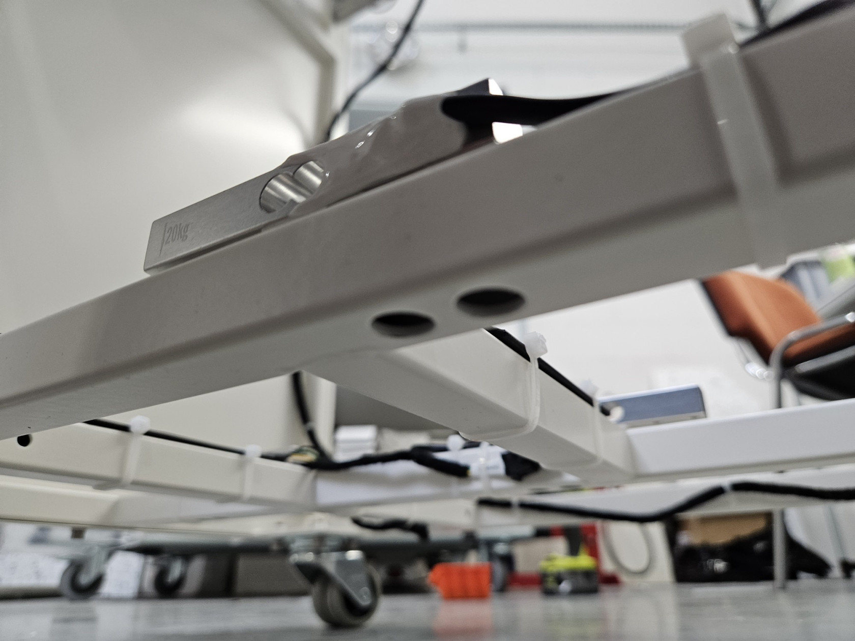
Step 4 Unscrew sensor form frame
|
|
|
|
|
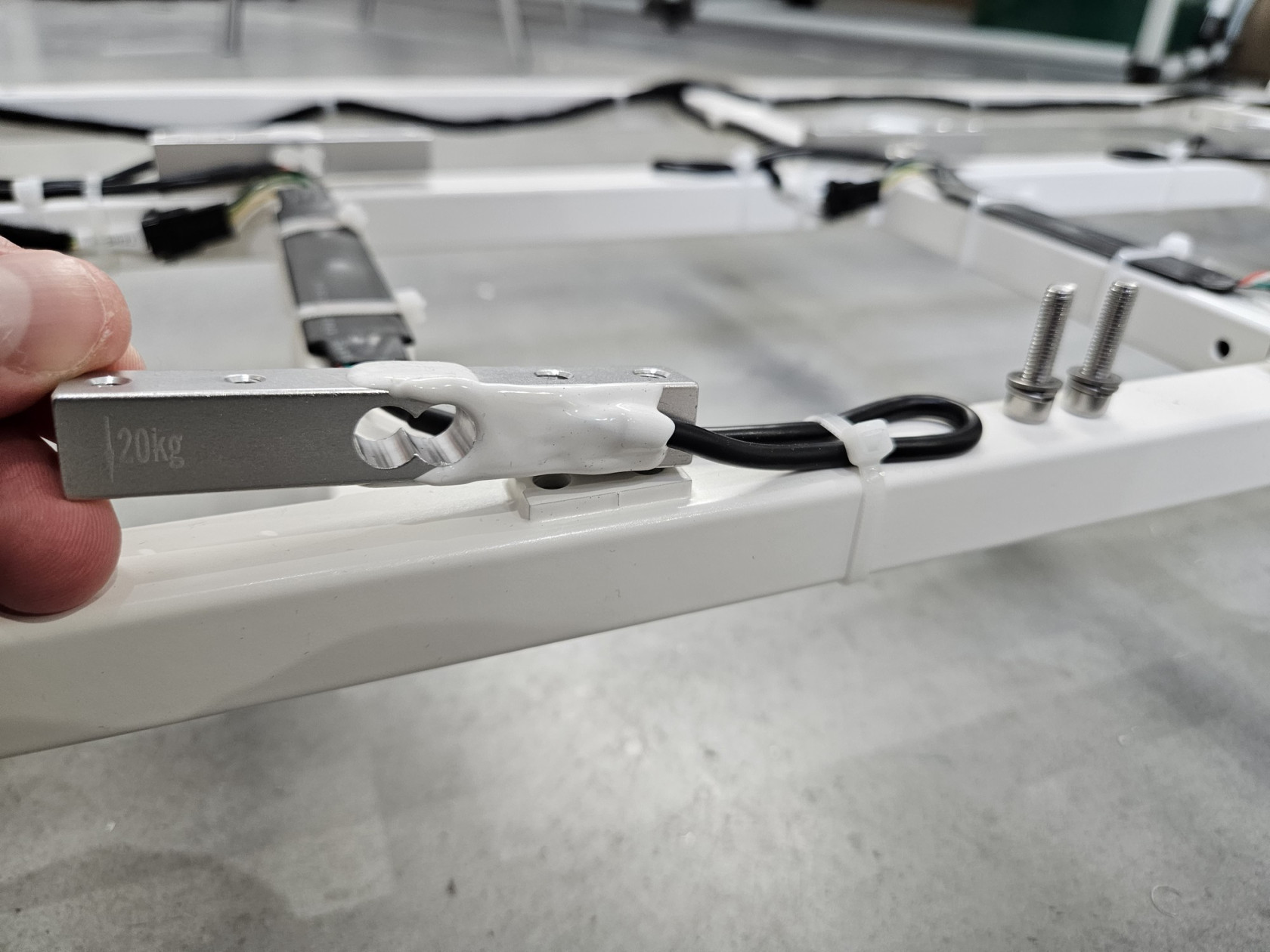
Step 5 Set new sensor
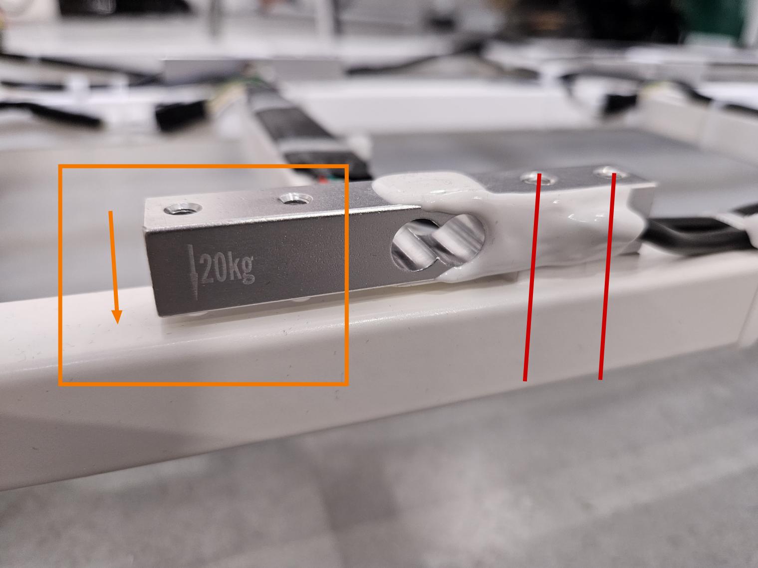
Pay special attention to the direction! The beam has an arrow drawn on it. This arrow should point down and be on the opposite side of the mounting screws to the frame! (see photo below)
On the front of the device, the arrow should be on the left and on the back on the right.
|
 |
Step 6 Secure cable and PCB with zippers
|
|
|
Step 7 Plug in a new sensor
|
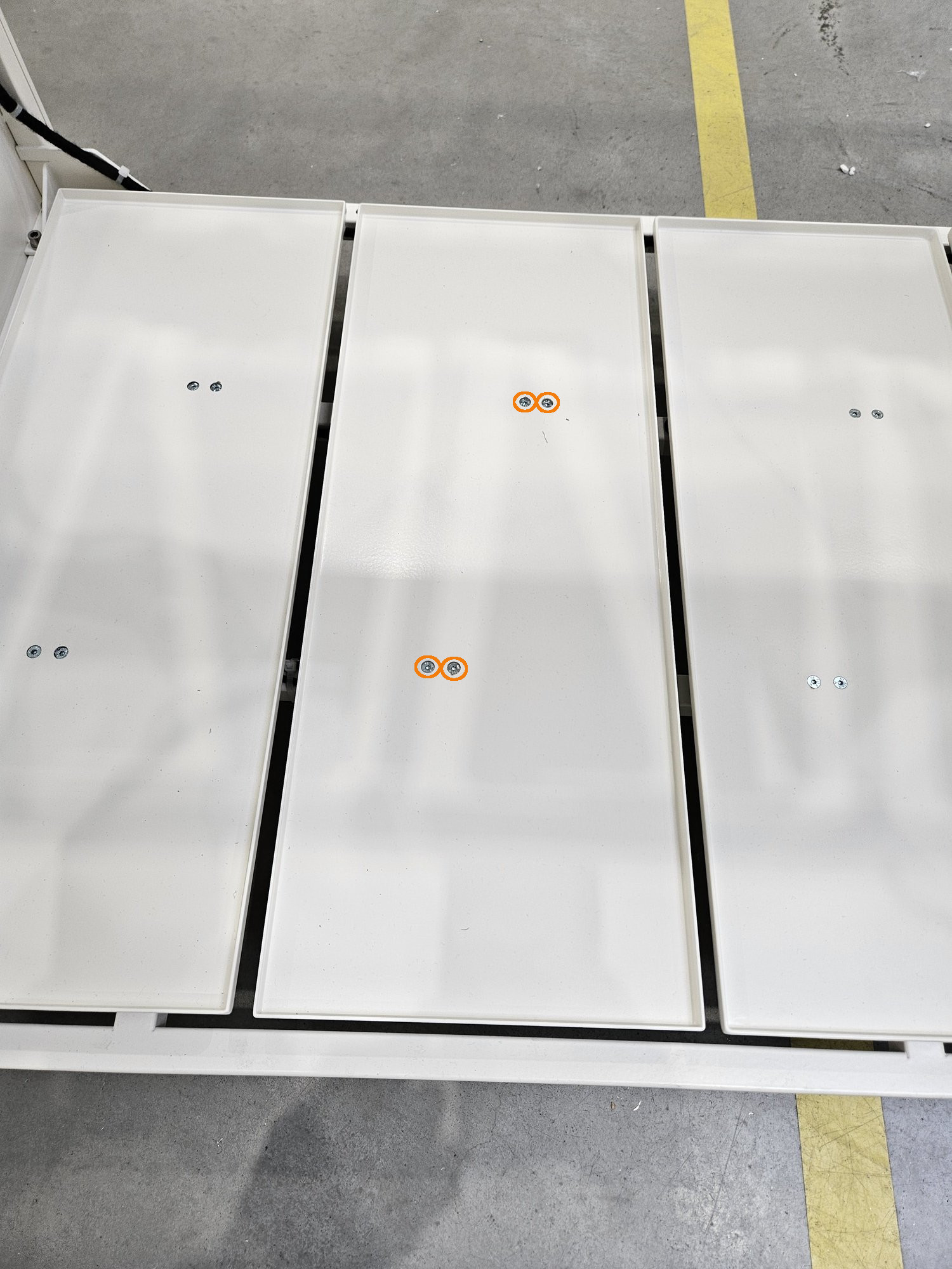
Step 8 Screw flor again
The floor is not symmetrical! Orient it similarly to the others!
 |
Step 9 Wieght calibration
Full calibration is required after load cell replacement. THIS IS A DIFFERENT CALIBRATION THAN ZERO CALIBRATION FROM THE MENU. Right now there is no possible full calibration from user menu.
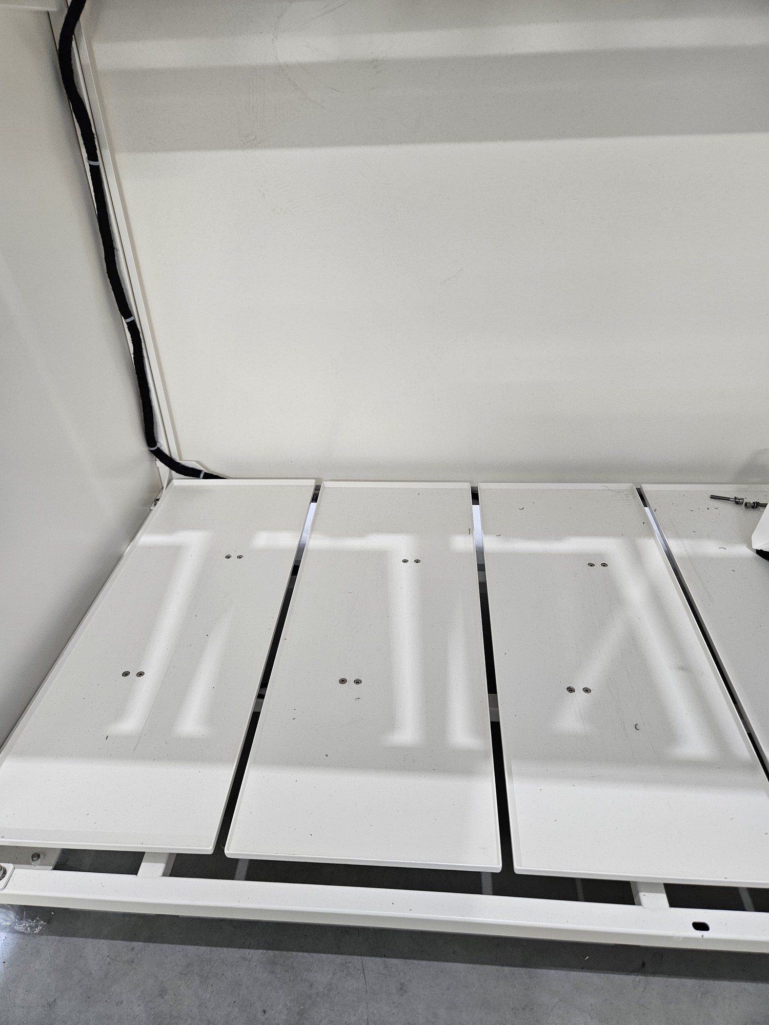
Calibration consists of 4 stages
1. empty beam
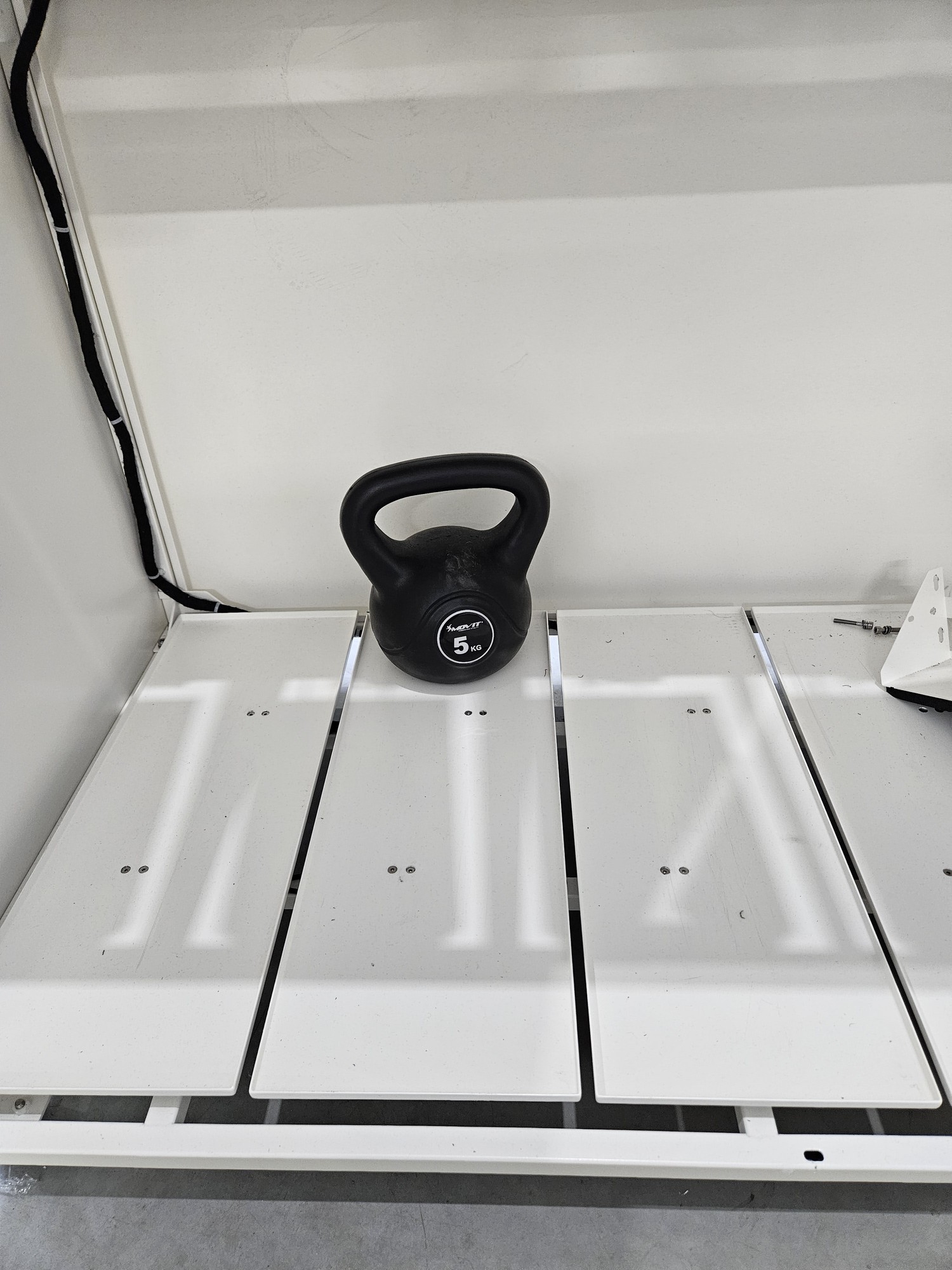
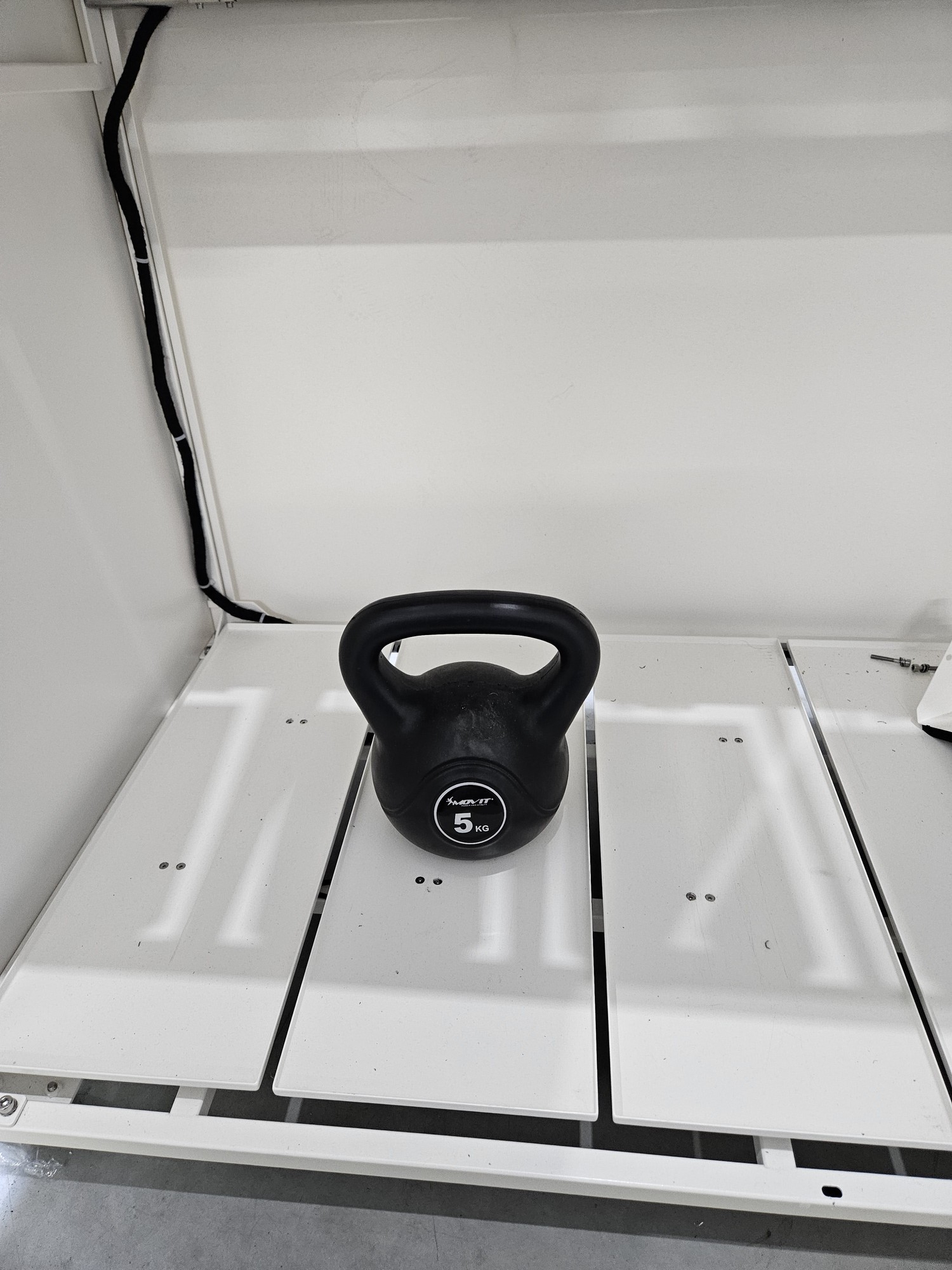
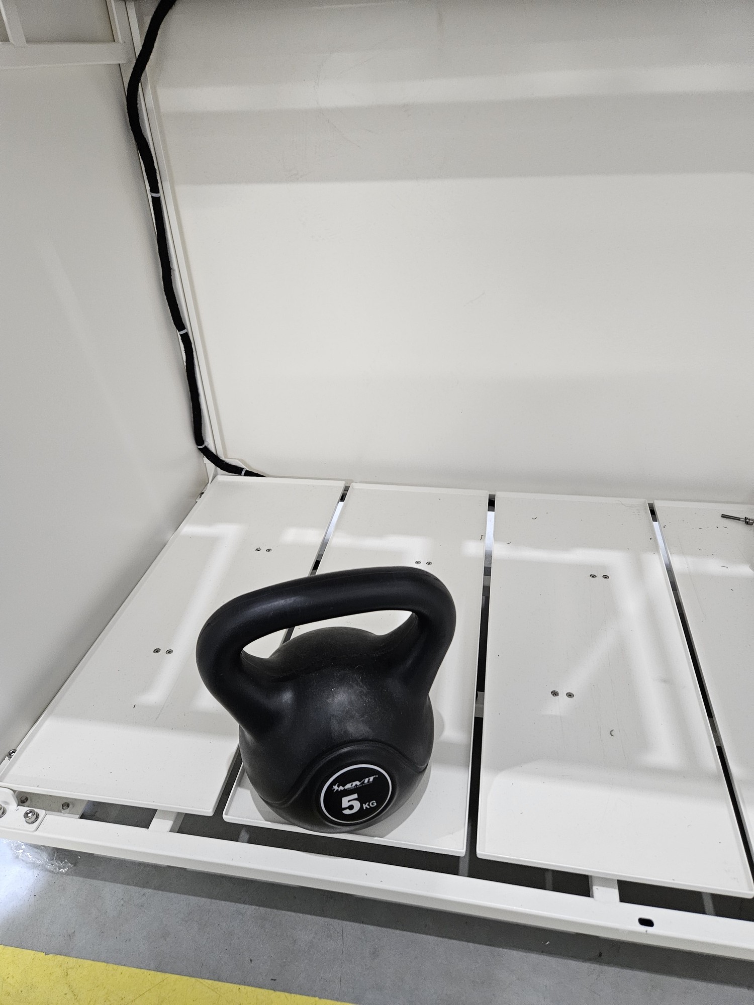
2. load placed at the back
3. load placed in the middle
4. load placed at the front
 |
|
 |
|
 |
|
 |
Replace motors mechanism Smartb
|
In this document you will find a description how to replace the throw flaps motors system in the Smartb
|
You will need:
|
Before replacing disconnect device from the power supply!
With practice, some points can be omitted, but the simplest path will be described here
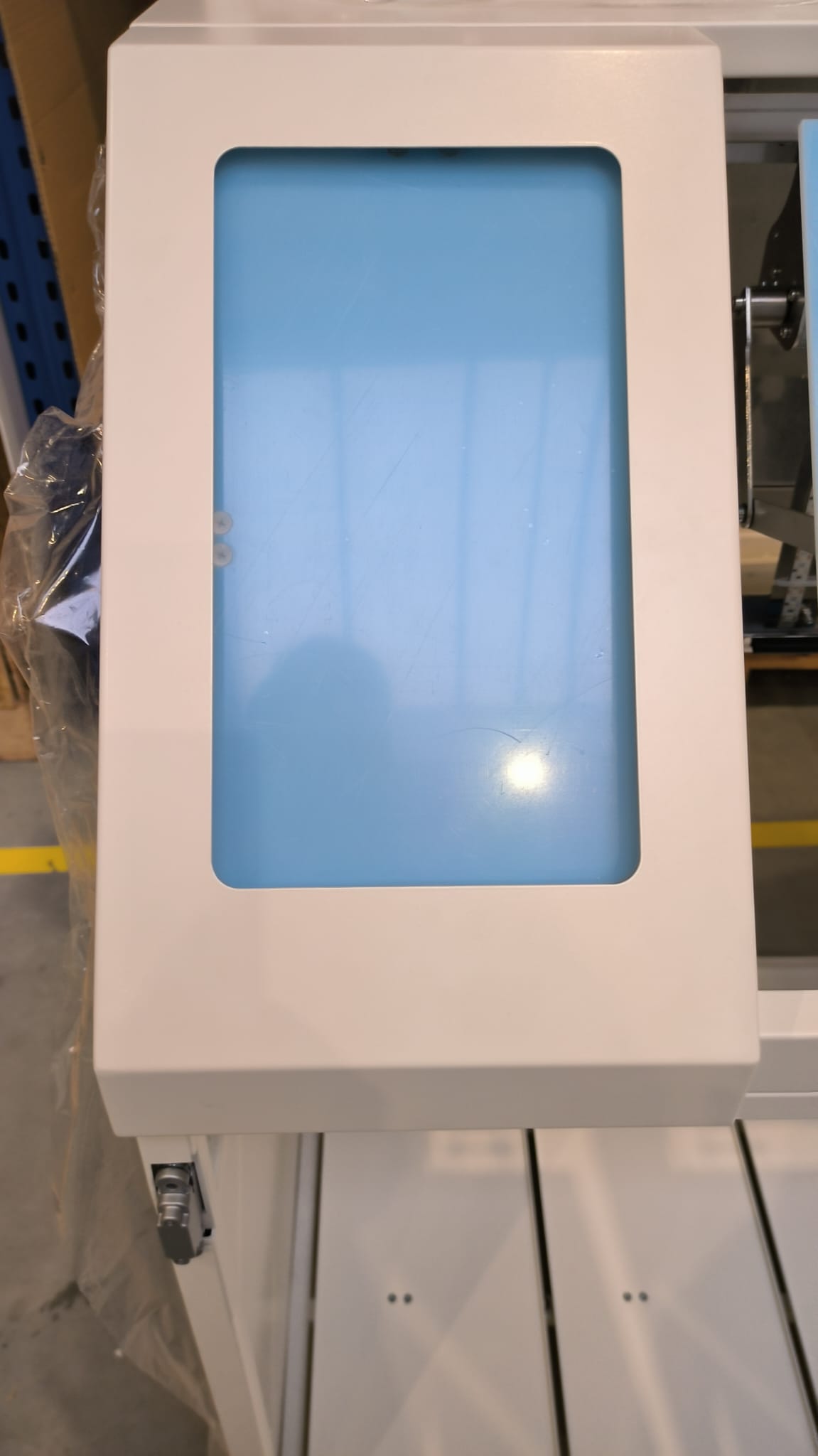
Step 1 Remove metal cover with shape
|
  |
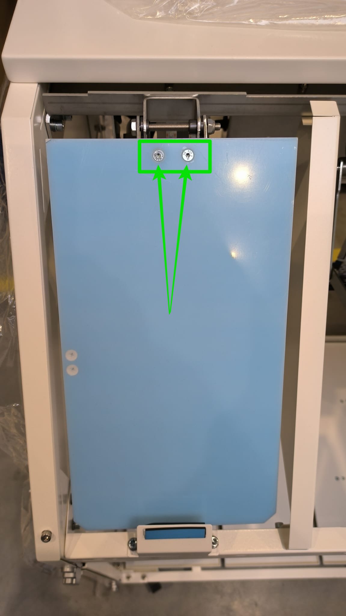
Step 2 Unscrew plastic flaps (optional)
|
  |
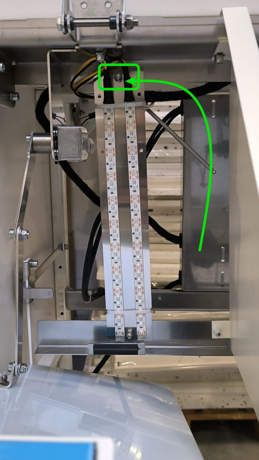
Step 3 Unscrew led holder (optional)
|
 |
 |
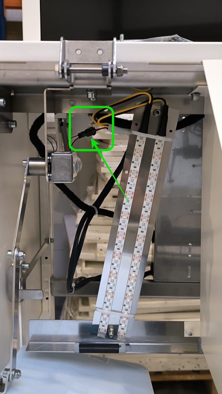
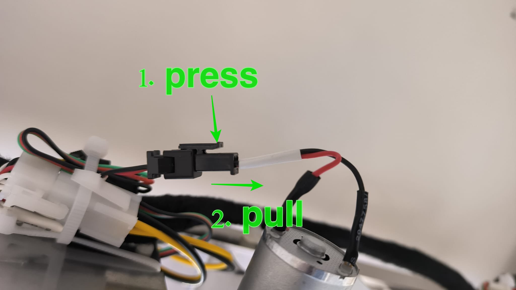
Step 4 Unplug motor cable
|
 |
|
Never pull the cables, only the plastic connector! |
|
|
|
|
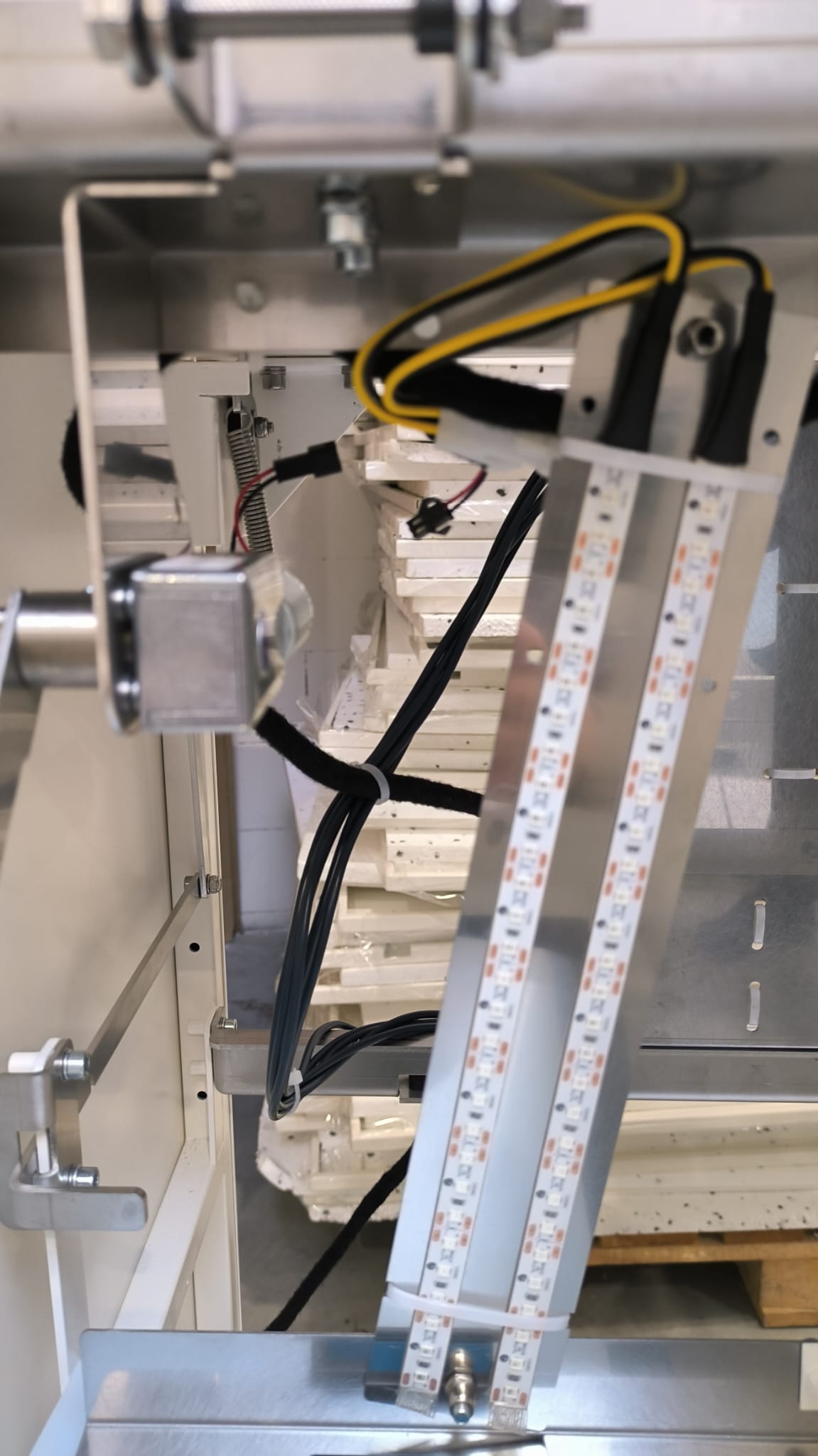
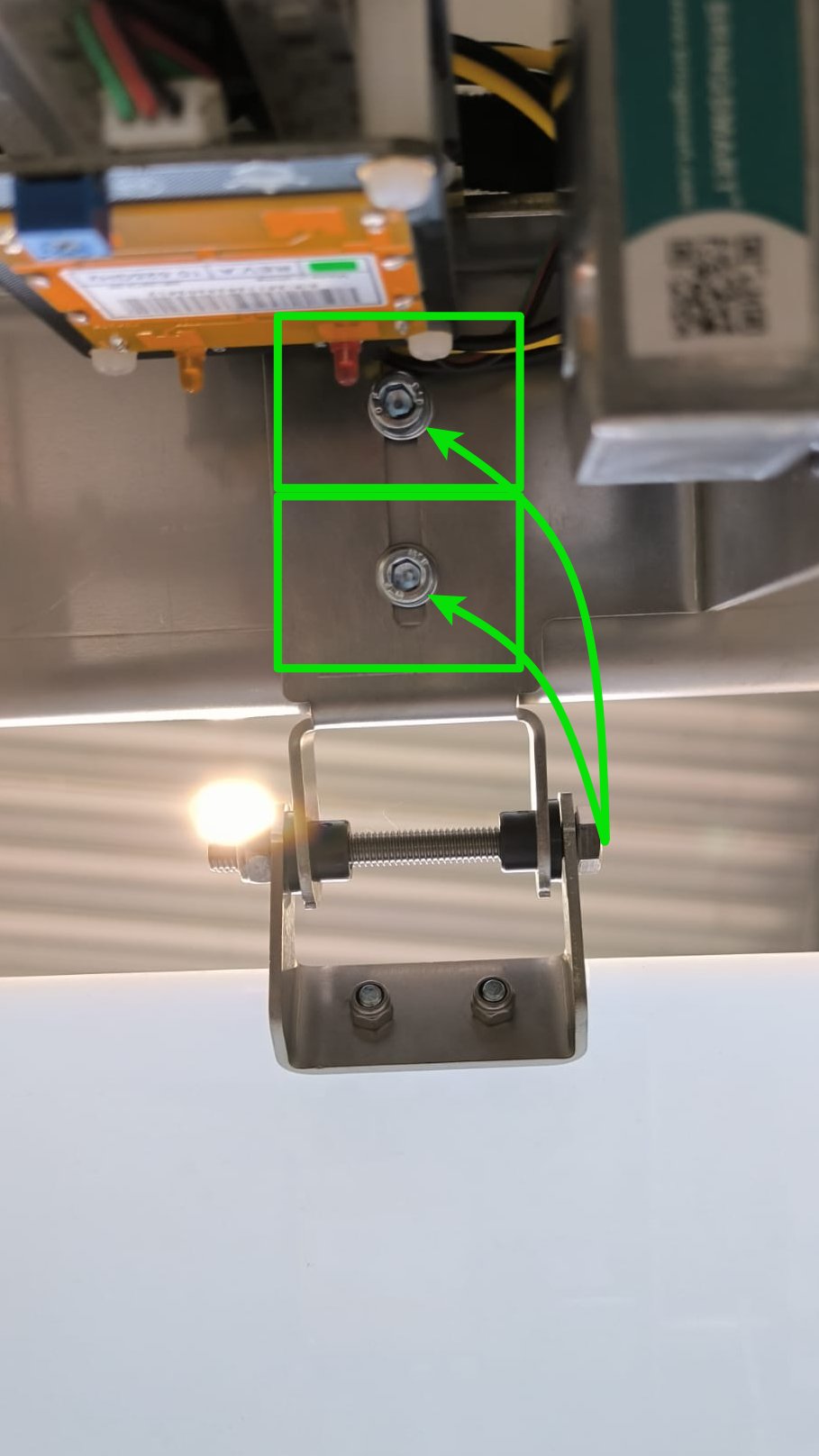
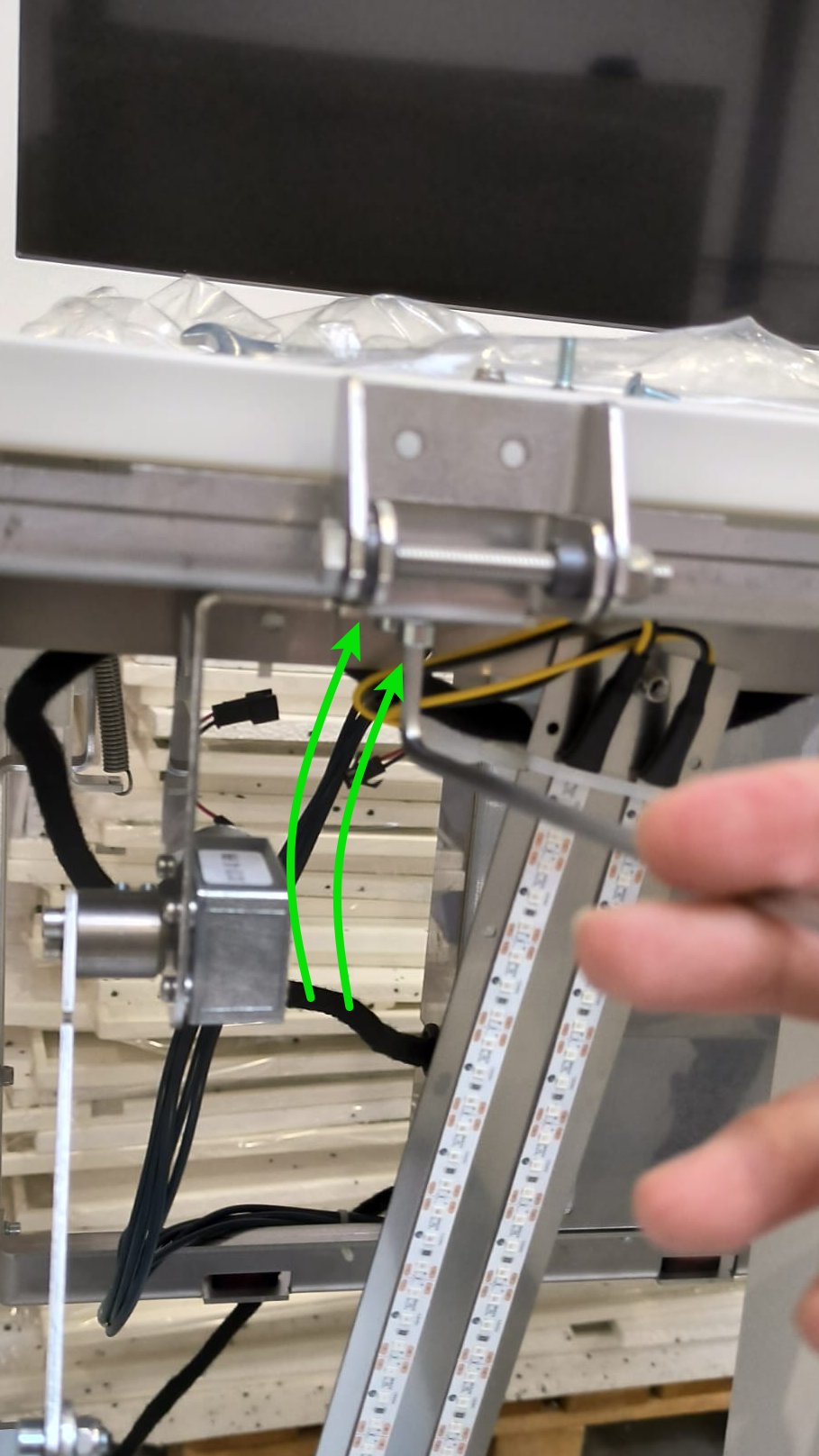
Step 5 Unscrew motor mechanism
|
 |
 |
Step 6 Now you can replace with new mechanism and assembly with opposite direction of the points
|
|
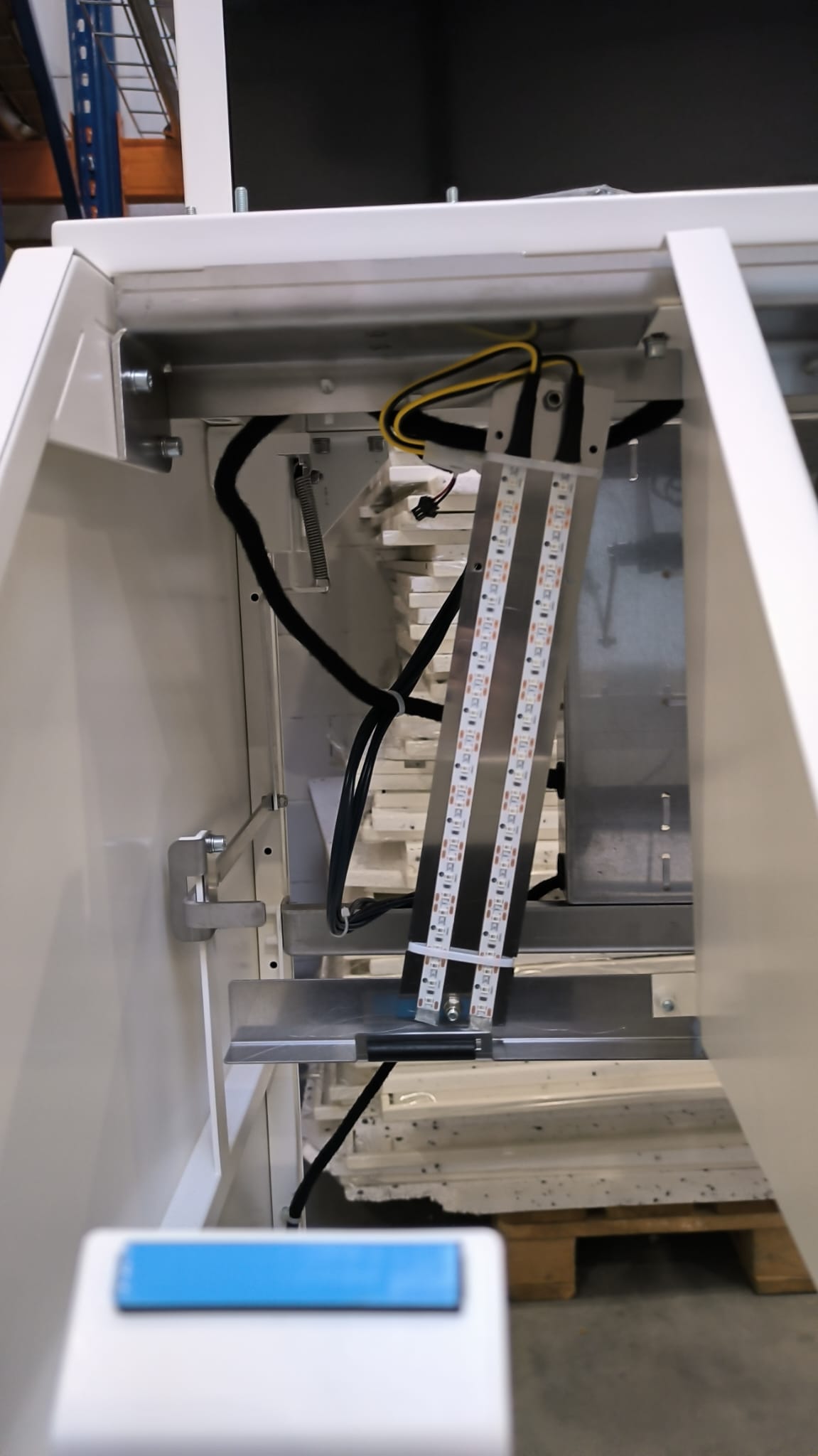 |
|
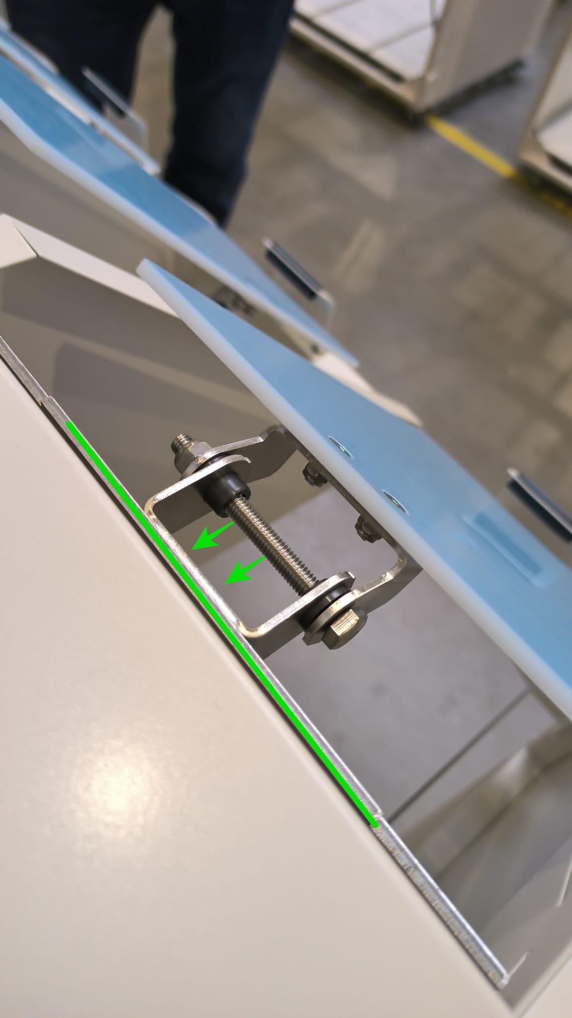 |
Checklist after replace:
- no screws remain
- motor work properly on full range in proper direction
- LEDs works OK
- person detect system works OK (on bin 2 and 4)
Smartb motors - how it works
<Do przeredagowania i translacji>
Sterowanie silnikami w smartb bazuje na pomiarze prądu i czasach ruchu. Nie ma w tym układzie krańcówek położenia skrajnego.
Działa to tak, że logika wysterowuje ruch silnika w zadanym kierunku i czeka aż na silniku wystąpi pomiar prądu powyżej 1A (tzn, że coś blokuje dalszy ruch silnika, albo jest to odbojnik skrajny w urządzeniu albo coś innego)
Dodatkowo na początku ruchu uruchamiany jest timer który odlicza do 1s, jeżeli silnik nie osiągnie prądu powyżej 1A w czasie krótszym niż 1s to jest emitowy błąd TIMEOUT (S003). Źródłem braku prądu w czasie 1s może być awaria silnika lub silnik nie jest podłączony.
Zwykle normalny ruch silnika trwa ok. 600ms.
Jeżeli silnik osiągnie prąd 1A w czasie krótszym niż 450ms to zwykle znaczy, ze coś blokuje jego ruch. Jeżeli taki stan (osiągnięcie prądu poniżej 450ms) wystąpi 3x pod rząd to emituje błąd UNDERTIME (S002)
Po wystąpieniu błędu TIMEOUT lub UNDERTIME silnik zatrzymuje się i LED świeci się na żółto.
Co ważne, po wejściu w tryb serwisowy wszystkie silniki kasują swoją flagę o błędzie i próbują wykonać ruch ponownie wg. w/w opisu.
The touch screen for customers
VIDEO TUTORIAL
DESCRIPTION
The touch screen is your tool to connect with the device. The main screen displays four circular icons - these are fractions symbols. Here you will find the name of the particular fraction and the fill level indicator. Thanks to this you will know how much more space is left in each inner bin.
The touch screen also display a message when the bin is full and it needs to be emptied.
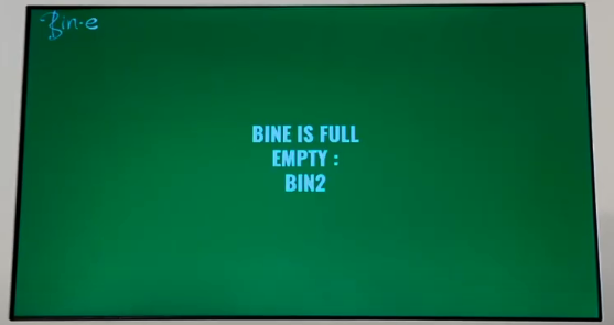
In the bottom right corner you will find pink lettering "How to use?" - it's the brief instruction of how to use Bin-e and what to avoid when you using it.
In addition, messages regarding, possible errors also appear on a touch screen. So if any error occurs - you can click "return to work" button and the device will retry the failed operation. If the error persist after this attempt - you should call the technical support.
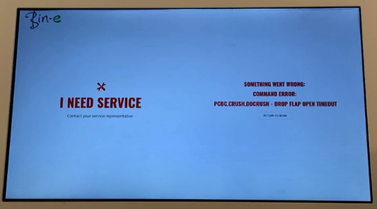
In the upper right corner there is a menu button. After clicking it a menu will unfold.
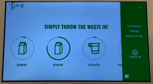
First we have the section "Connection" - it's where we can see if the device is connected to the internet and check the status of this connection. You can also check whether the device is connected through the wifi or GSM model. You can connect the device to any wifi network that meets these parameters : 2.4 GHZ IEEE 802.11 BGN. To connect to wifi proceed as indicated as any mobile device.
The next section is "Settings". Here we can change the device language and see information about the software version.
The last section of the menu is "Service mode". But only service technicians have access to it.
At the very bottom there is a button that turns off the device.