# Replace weight sensor

<table border="1" id="bkmrk-czasami-co%C5%9B-si%C4%99-pops" style="border-collapse: collapse; width: 100%; border-width: 1px; border-style: hidden;"><colgroup><col style="width: 50%;"></col><col style="width: 50%;"></col></colgroup><tbody><tr><td style="border-width: 1px;">In this document you will find a description how to replace the weight sensor in the Smartb

</td><td style="border-width: 1px;">You will need:

- a new weight sensor kit
- a set of allen keys
- trimmers
- cutters

</td></tr></tbody></table>

<p class="callout danger">Before replacing disconnect device from the power supply!</p>

---

#### **Step 1** Unscrew the top floor 

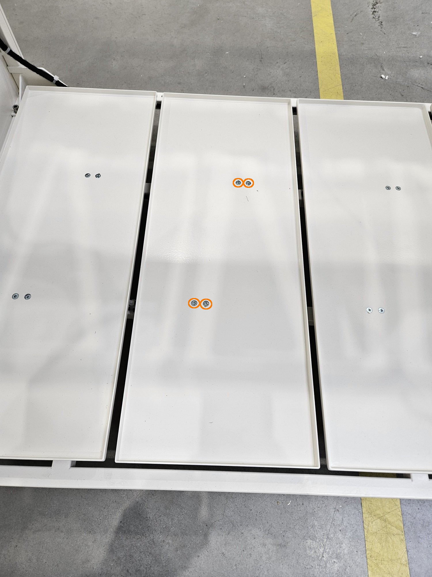
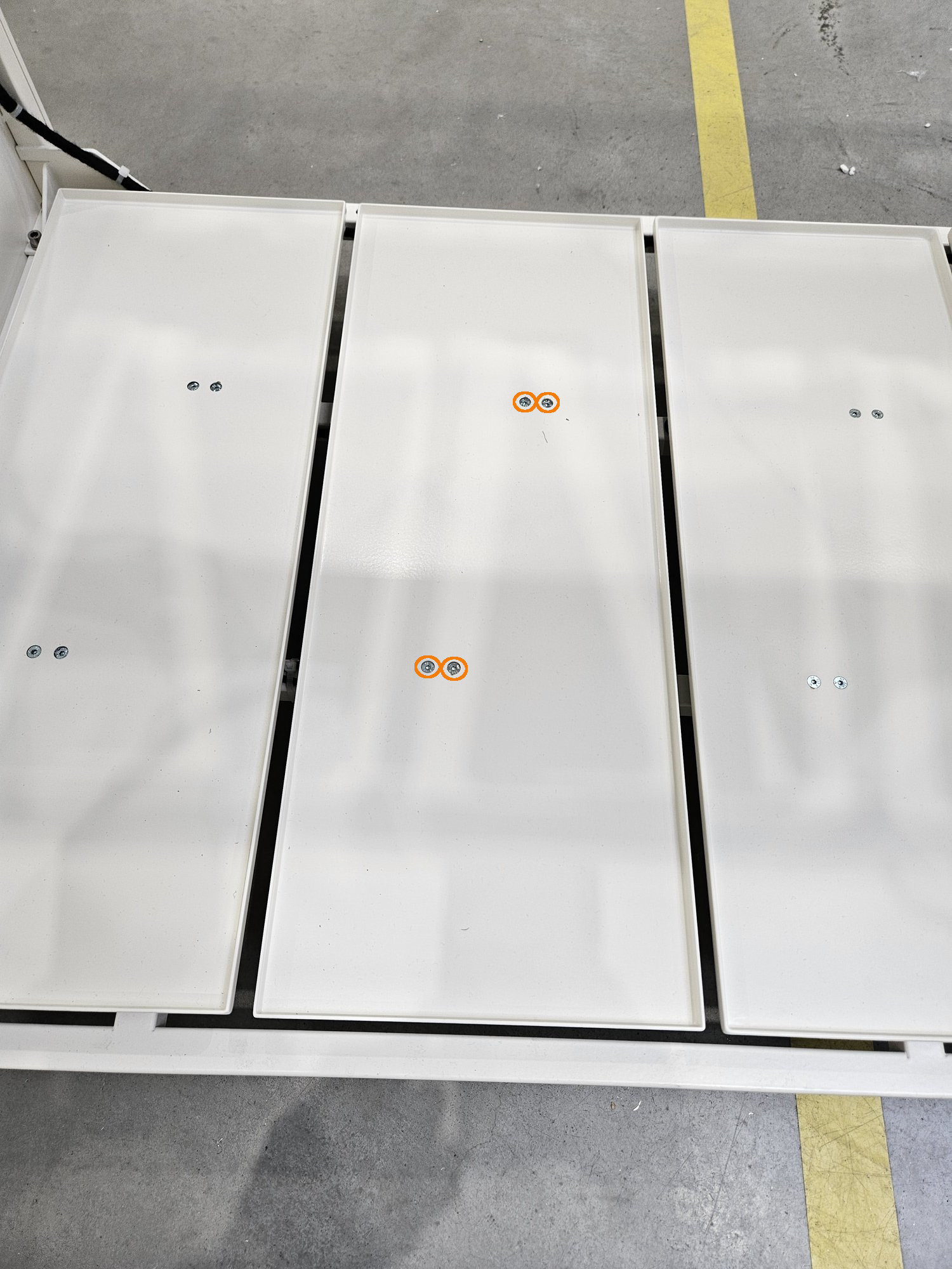
<table border="1" id="bkmrk-the-top-floor-is-bol" style="border-collapse: collapse; width: 100%; border-width: 1px; border-style: hidden;"><colgroup><col style="width: 50%;"></col><col style="width: 50%;"></col></colgroup><tbody><tr><td>- The top floor is bolted directly from the strain gauge beams
- Unscrew the 4 screws marked on the picture

</td><td>[![1.jpg](https://docs.bine.world/uploads/images/gallery/2023-11/scaled-1680-/h6WN2VgvyqWfRjB5-1.jpg)](https://docs.bine.world/uploads/images/gallery/2023-11/h6WN2VgvyqWfRjB5-1.jpg)</td></tr></tbody></table>


---

#### **Step 2** Unplug the sensor

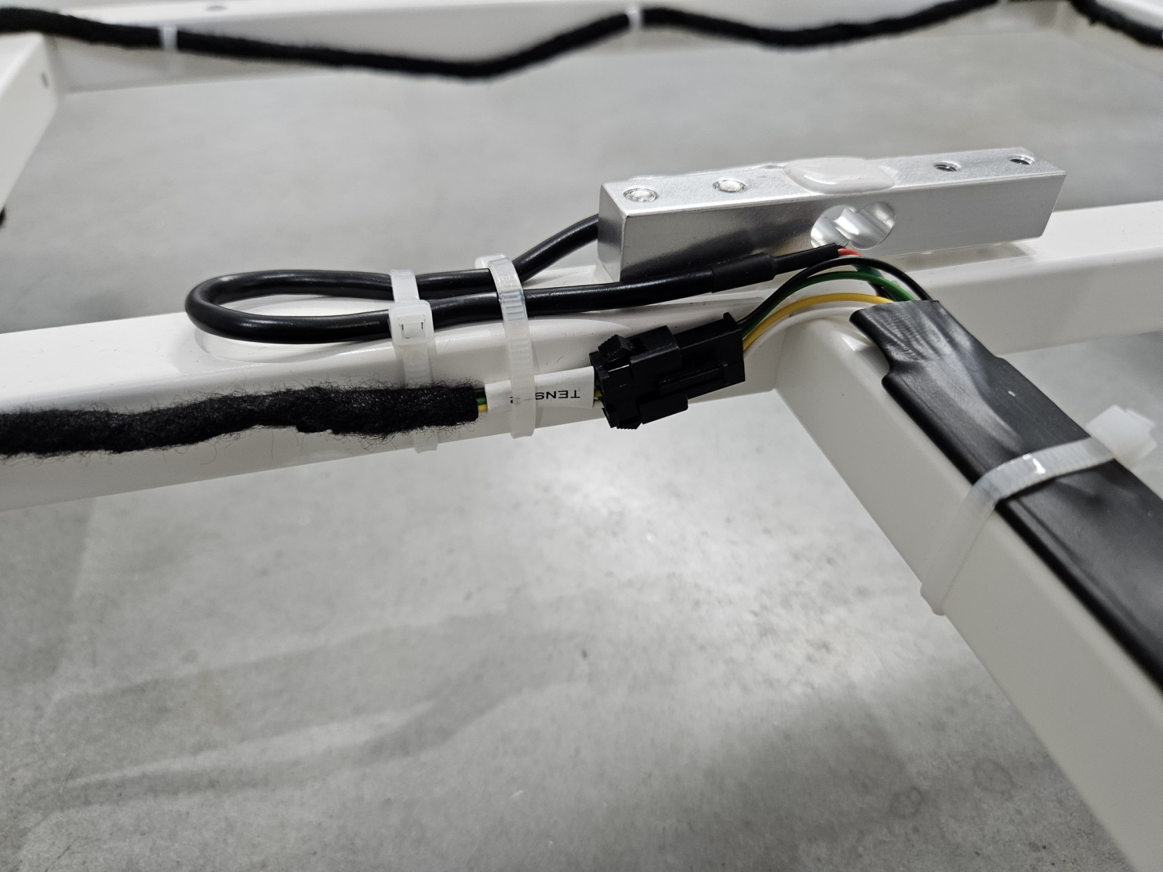
<table border="1" id="bkmrk-unplug-the-sensor" style="border-collapse: collapse; width: 100%; border-width: 1px; border-style: hidden;"><colgroup><col style="width: 50%;"></col><col style="width: 50%;"></col></colgroup><tbody><tr><td>- Unplug the sensor

</td><td>[![20231117_091935.jpg](https://docs.bine.world/uploads/images/gallery/2023-11/scaled-1680-/70ME9Th4eTsJzcgi-20231117-091935.jpg)](https://docs.bine.world/uploads/images/gallery/2023-11/70ME9Th4eTsJzcgi-20231117-091935.jpg)</td></tr></tbody></table>

---

#### **Step 3** Remove zippers

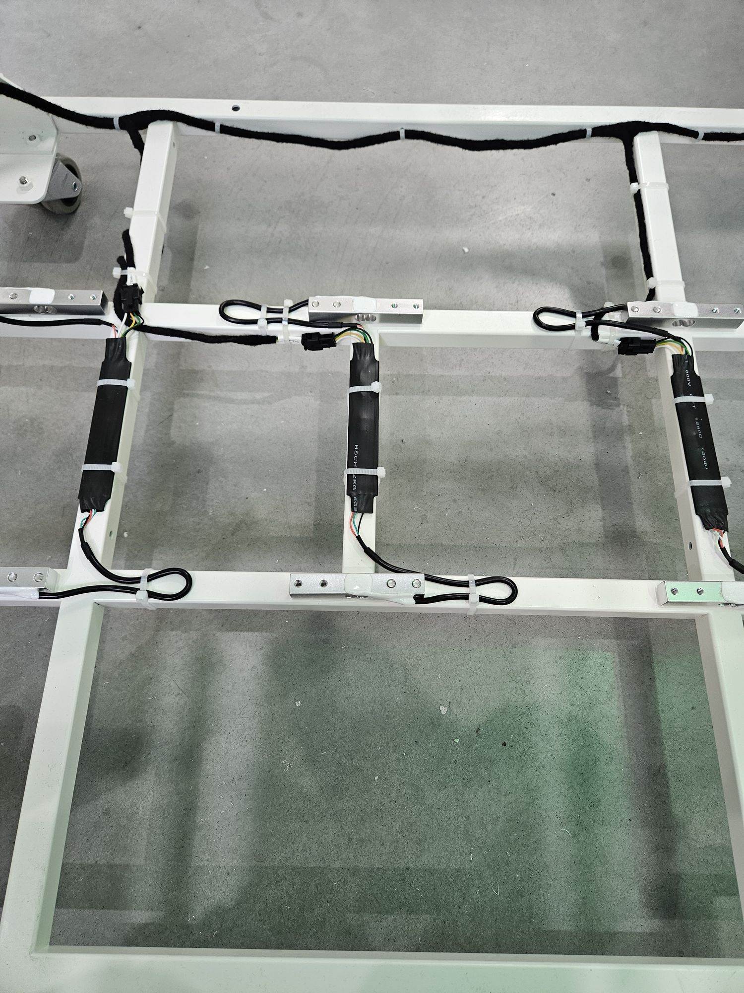
<table border="1" id="bkmrk--2" style="border-collapse: collapse; width: 100%; border-width: 1px; border-style: hidden;"><colgroup><col style="width: 50%;"></col><col style="width: 50%;"></col></colgroup><tbody><tr><td>  
</td><td>[![20231117_091525.jpg](https://docs.bine.world/uploads/images/gallery/2023-11/scaled-1680-/aRcLadXht2N8700Q-20231117-091525.jpg)](https://docs.bine.world/uploads/images/gallery/2023-11/aRcLadXht2N8700Q-20231117-091525.jpg)</td></tr></tbody></table>

---

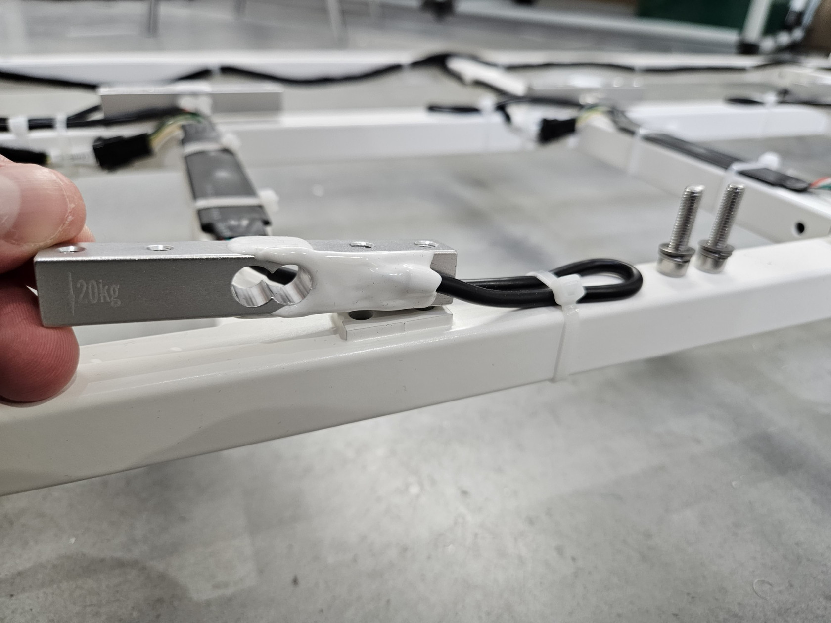
#### **Step 4** Unscrew sensor form frame

<table border="1" id="bkmrk--8" style="border-collapse: collapse; width: 100%; border-width: 1px; border-style: hidden;"><colgroup><col style="width: 50%;"></col><col style="width: 50%;"></col></colgroup><tbody><tr><td style="border-width: 1px;">- There are two bolt (for each load cell) form bottom (alen key 4)

</td><td style="border-width: 1px;">[![ZeVADu0vXqx2c2nE-20231117-091736.jpg](https://docs.bine.world/uploads/images/gallery/2023-11/scaled-1680-/nzYhjKCmNogtv9pg-zevadu0vxqx2c2ne-20231117-091736.jpg)](https://docs.bine.world/uploads/images/gallery/2023-11/nzYhjKCmNogtv9pg-zevadu0vxqx2c2ne-20231117-091736.jpg)</td></tr><tr><td style="border-width: 1px;"></td><td style="border-width: 1px;">[![uSVs6HyEOUR9hmRp-20231117-091914.jpg](https://docs.bine.world/uploads/images/gallery/2023-11/scaled-1680-/lhANya5U3LgQ7teH-usvs6hyeour9hmrp-20231117-091914.jpg)](https://docs.bine.world/uploads/images/gallery/2023-11/lhANya5U3LgQ7teH-usvs6hyeour9hmrp-20231117-091914.jpg)

</td></tr></tbody></table>

---

#### **Step 5** Set new sensor

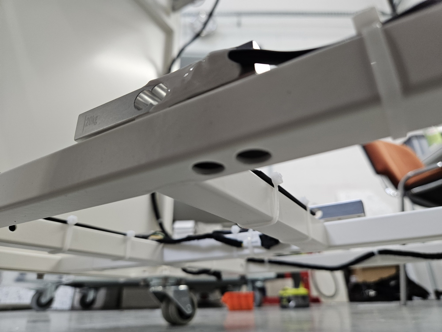
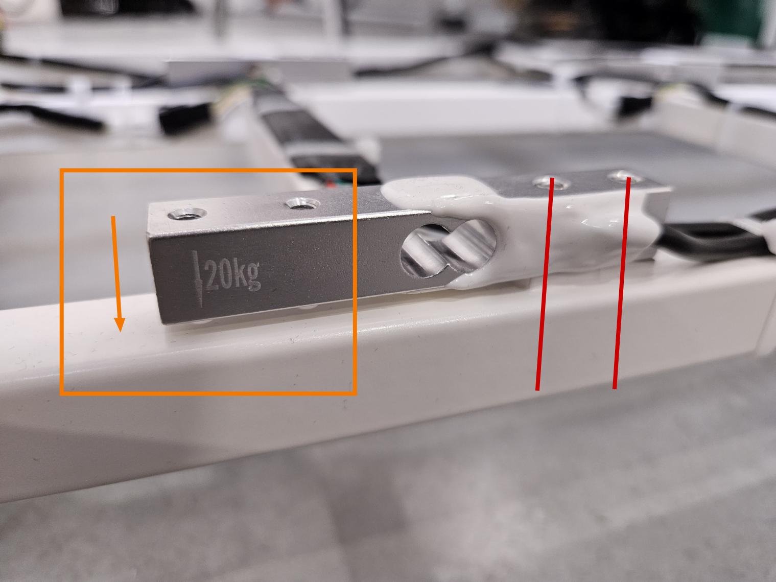
<p class="callout warning">Pay special attention to the direction! The beam has an arrow drawn on it. This arrow should point down and be on the opposite side of the mounting screws to the frame! (see photo below)  
On the front of the device, the arrow should be on the left and on the back on the right.</p>

<table border="1" id="bkmrk-najpierw-u%C5%82%C3%B3%C5%BC-belki-" style="border-collapse: collapse; width: 100%; border-width: 1px; border-style: hidden;"><colgroup><col style="width: 50%;"></col><col style="width: 50%;"></col></colgroup><tbody><tr><td>- first place the beams in their final positions
- screw the first one (closer to the front door)
- then the second one at the back similarly to the description (on the back it is on the other side)

</td><td>[![20231117_0915451.jpg](https://docs.bine.world/uploads/images/gallery/2023-11/scaled-1680-/UbbyQpbq1GIg9jll-20231117-0915451.jpg)](https://docs.bine.world/uploads/images/gallery/2023-11/UbbyQpbq1GIg9jll-20231117-0915451.jpg)</td></tr></tbody></table>

---

#### **Step 6** Secure cable and PCB with zippers

<table border="1" id="bkmrk-asdasd" style="border-collapse: collapse; width: 100%; border-width: 1px; border-style: hidden;"><colgroup><col style="width: 50%;"></col><col style="width: 50%;"></col></colgroup><tbody><tr><td>- 

</td><td>[![20231117_091525.jpg](https://docs.bine.world/uploads/images/gallery/2023-11/scaled-1680-/aRcLadXht2N8700Q-20231117-091525.jpg)](https://docs.bine.world/uploads/images/gallery/2023-11/aRcLadXht2N8700Q-20231117-091525.jpg)</td></tr></tbody></table>

---

#### **Step 7** Plug in a new sensor

<table border="1" id="bkmrk--15" style="border-collapse: collapse; width: 100%; border-width: 1px; border-style: hidden;"><colgroup><col style="width: 50%;"></col><col style="width: 50%;"></col></colgroup><tbody><tr><td>  
</td><td>[![20231117_091935.jpg](https://docs.bine.world/uploads/images/gallery/2023-11/scaled-1680-/70ME9Th4eTsJzcgi-20231117-091935.jpg)](https://docs.bine.world/uploads/images/gallery/2023-11/70ME9Th4eTsJzcgi-20231117-091935.jpg)</td></tr></tbody></table>

---

#### **Step 8** Screw flor again

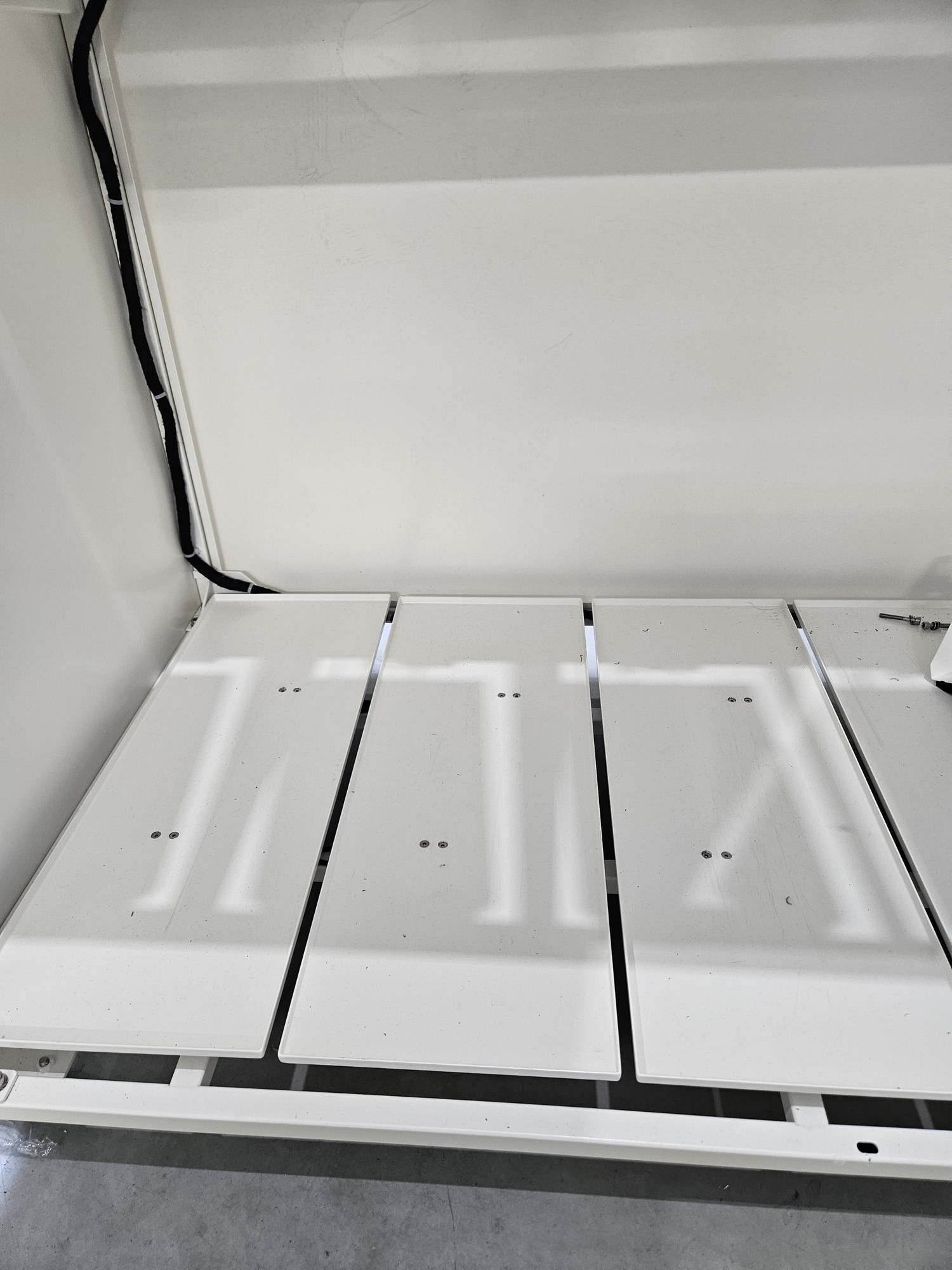
<p class="callout warning">The floor is not symmetrical! Orient it similarly to the others!</p>

<table border="1" id="bkmrk-%C2%A0-5" style="border-collapse: collapse; width: 100%; height: 29.6px; border-width: 1px; border-style: hidden;"><colgroup><col style="width: 50%;"></col><col style="width: 50%;"></col></colgroup><tbody><tr style="height: 29.6px;"><td style="height: 29.6px;"> </td><td style="height: 29.6px;">[![h6WN2VgvyqWfRjB5-1.jpg](https://docs.bine.world/uploads/images/gallery/2023-11/scaled-1680-/00piKditb3Fu7nNE-h6wn2vgvyqwfrjb5-1.jpg)](https://docs.bine.world/uploads/images/gallery/2023-11/00piKditb3Fu7nNE-h6wn2vgvyqwfrjb5-1.jpg)</td></tr></tbody></table>

---

#### **Step 9** Wieght calibration

<p class="callout info">Full calibration is required after load cell replacement. THIS IS A DIFFERENT CALIBRATION THAN ZERO CALIBRATION FROM THE MENU. Right now there is no possible full calibration from user menu.</p>

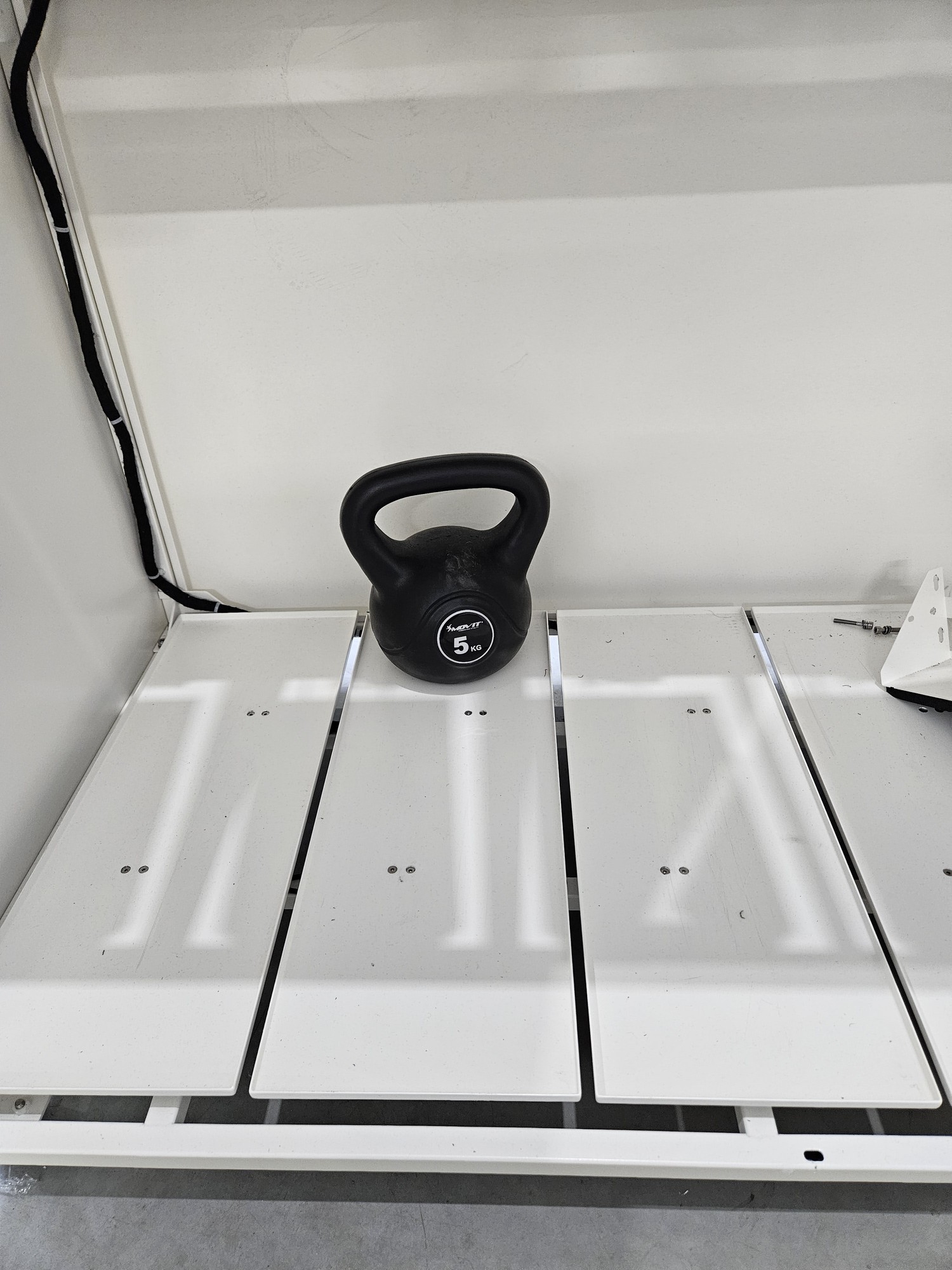
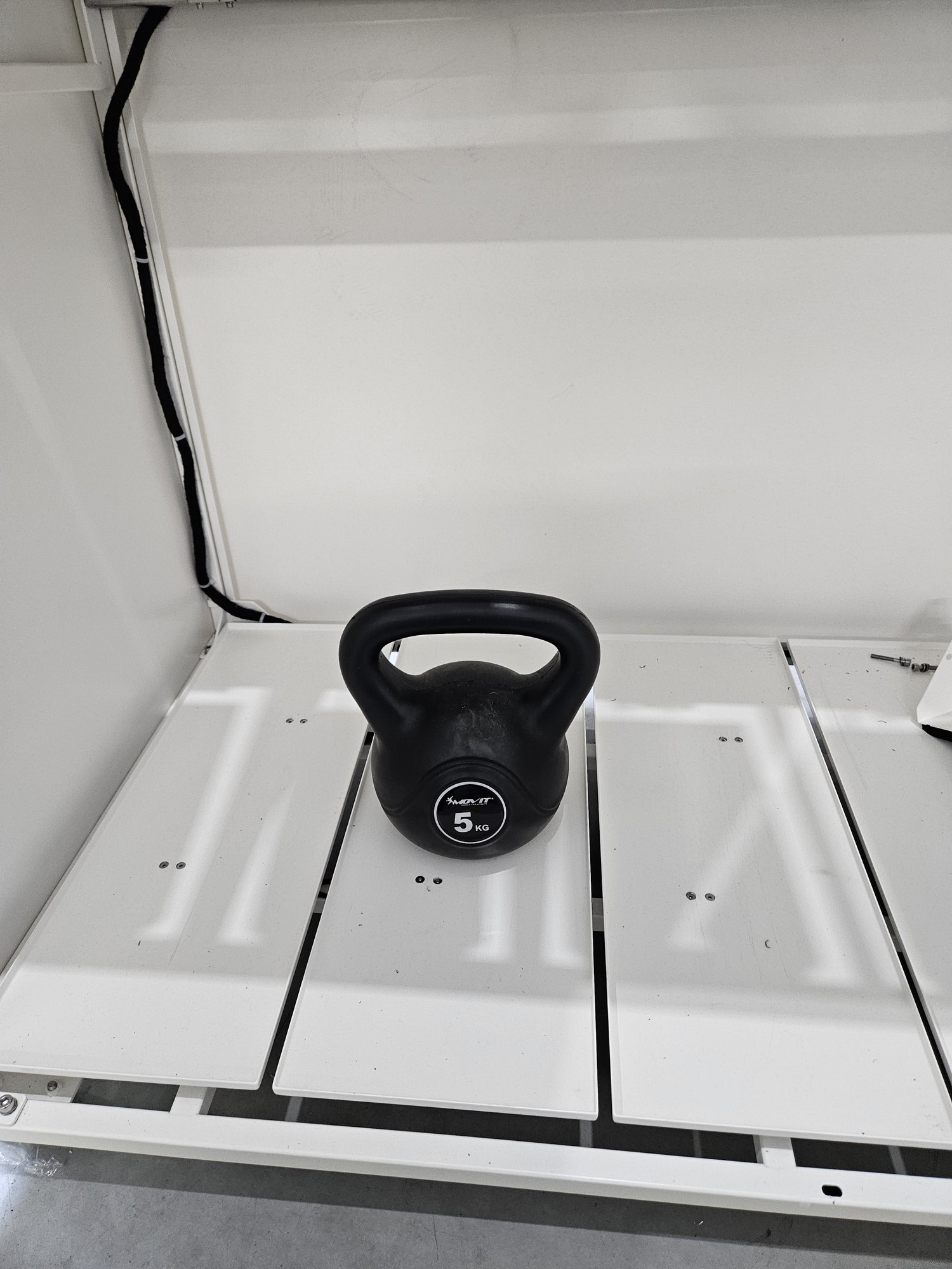
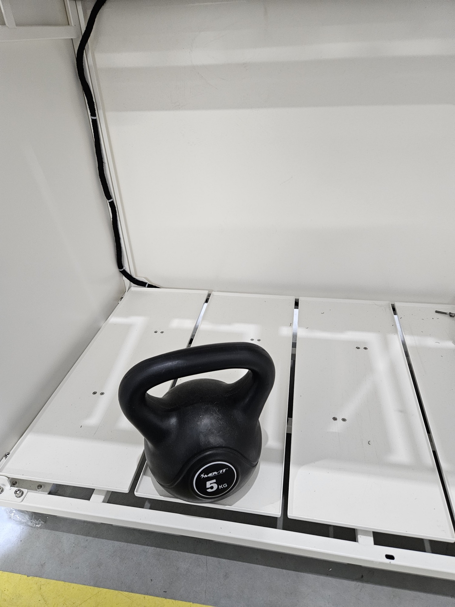
<p class="callout warning">Calibration consists of 4 stages  
1. empty beam  
2. load placed at the back  
3. load placed in the middle  
4. load placed at the front</p>

<table border="1" id="bkmrk--19" style="border-collapse: collapse; width: 100%; border-width: 1px; border-style: hidden;"><colgroup><col style="width: 50%;"></col><col style="width: 50%;"></col></colgroup><tbody><tr><td>  
</td><td>[![pusta.jpg](https://docs.bine.world/uploads/images/gallery/2023-11/scaled-1680-/hhegjpQ4Ss5lIuOk-pusta.jpg)](https://docs.bine.world/uploads/images/gallery/2023-11/hhegjpQ4Ss5lIuOk-pusta.jpg)</td></tr><tr><td>  
</td><td>[![kalibracja tyl.jpg](https://docs.bine.world/uploads/images/gallery/2023-11/scaled-1680-/gpbQO7818iTjEneq-kalibracja-tyl.jpg)](https://docs.bine.world/uploads/images/gallery/2023-11/gpbQO7818iTjEneq-kalibracja-tyl.jpg)</td></tr><tr><td>  
</td><td>[![kalibracja srodek.jpg](https://docs.bine.world/uploads/images/gallery/2023-11/scaled-1680-/nwief27SWeFU7Pp7-kalibracja-srodek.jpg)](https://docs.bine.world/uploads/images/gallery/2023-11/nwief27SWeFU7Pp7-kalibracja-srodek.jpg)</td></tr><tr><td>  
</td><td>[![kalibracja przod.jpg](https://docs.bine.world/uploads/images/gallery/2023-11/scaled-1680-/aimtQpKXbQ6kNH3i-kalibracja-przod.jpg)](https://docs.bine.world/uploads/images/gallery/2023-11/aimtQpKXbQ6kNH3i-kalibracja-przod.jpg)</td></tr></tbody></table>